Apparatus and methods for drilling

a drilling apparatus and drilling method technology, applied in the direction of drilling composition, drilling/well accessories, chemistry apparatus and processes, etc., can solve the problems of reducing affecting the production capacity of formation, and adding to the friction associated pressure loss, so as to maintain the flow speed and cut

Inactive Publication Date: 2005-11-29
GASOLINEINE WELLSYST
View PDF28 Cites 2 Cited by
  • Summary
  • Abstract
  • Description
  • Claims
  • Application Information

AI Technical Summary

Benefits of technology

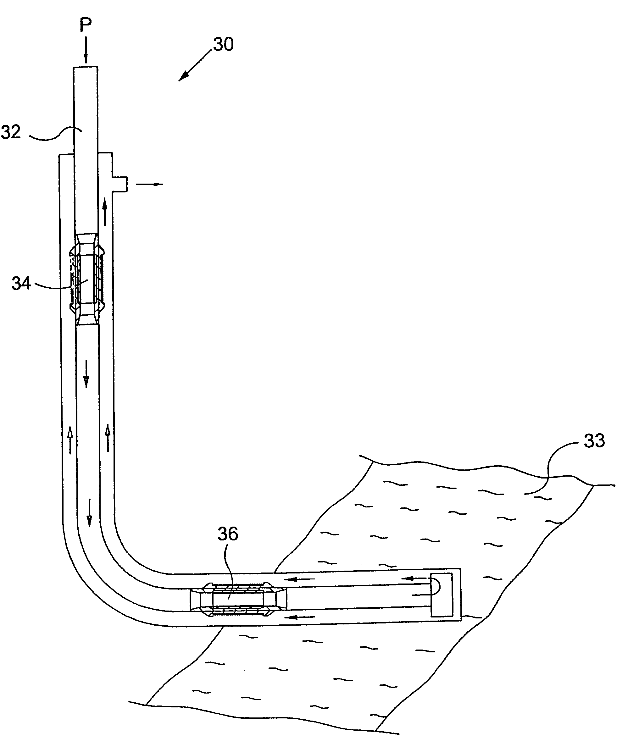
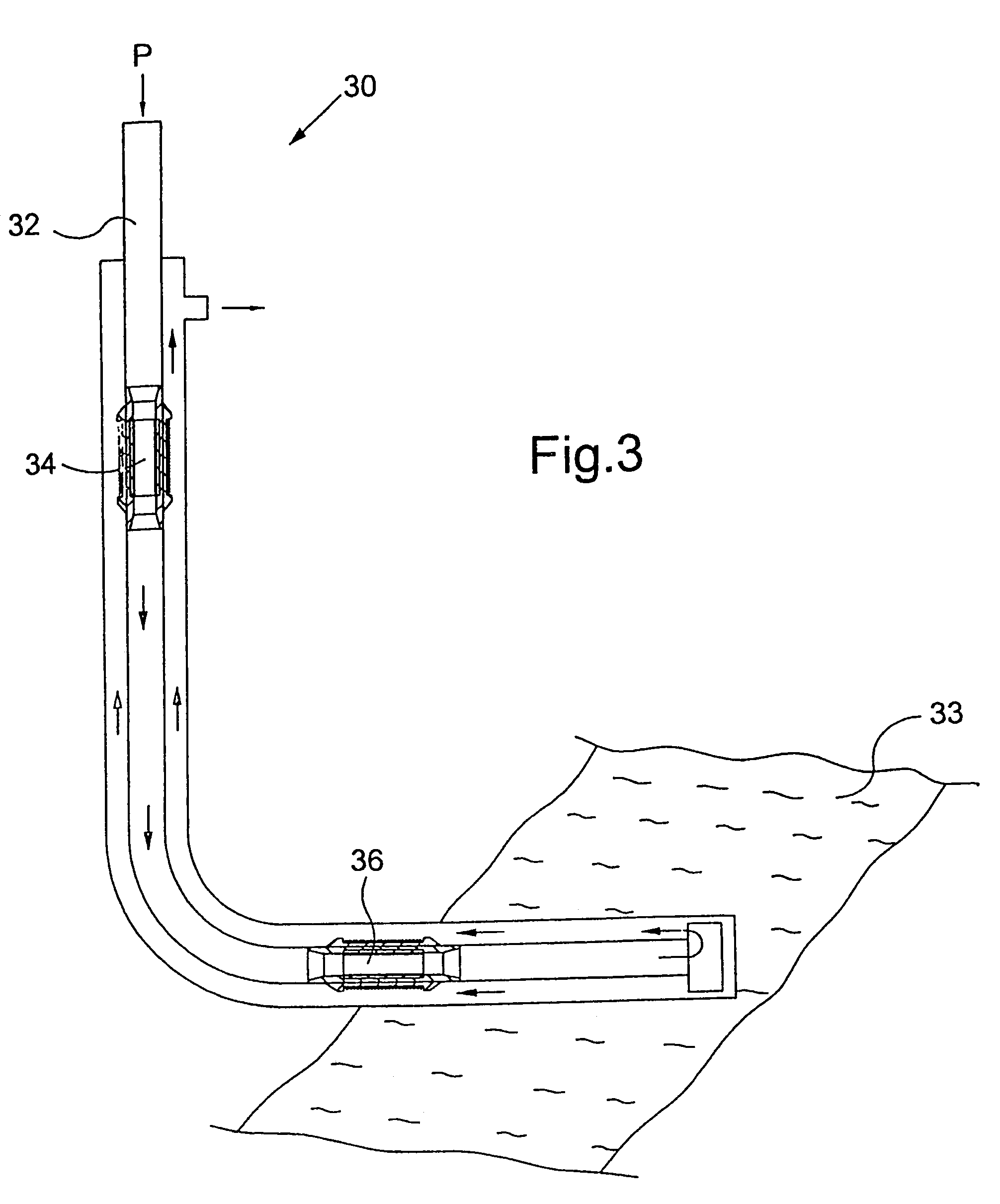
[0024]In one embodiment of the invention, a portion of the circulating drilling fluid may be permitted to flow directly from the drillstring bore to the annulus above the formation, and such diversion of flow may be particularly useful in boreholes of varying diameter, the changes in diameter typically being step increases in bore diameter. When the bore diameter increases, drilling fluid flow speed in the annulus will normally decrease, and the additional volume of fluid flowing directly from the drillstring bore into the annulus assists in maintaining flow speed and cuttings entrainment. This may be achieved by provision of one or more bypass subs in the string. The bypass subs may be selectively operable to provide fluid bypass only when considered necessary or desirable.

Problems solved by technology

This adds to natural friction associated pressure loss as experienced by any flowing fluid.
In addition to mechanical considerations, such as top drive torque ratings and drill pipe strength, the increase in ECD at the formation may reach a level where the mud damages the formation, and in particular reduces the productivity of the formation.
However, if the pressure differential exceeds a certain level, known as the fracture gradient, the mud will fracture the formation and begin to flow into the formation.
In addition to loss of drilling fluid, fracturing also affects the production capabilities of a formation.
However, this increases drilling costs, is often of limited effectiveness, and tends to reduce the production capabilities of the formation.
High mud pressure also has a number of undesirable effects on drilling efficiency.
In deviated bores the drillstring may lie in contact with the bore wall, and if the bore intersects a lower pressure formation the fluid pressure acting on the remainder of the string will tend to push the string against the bore wall, significantly increasing drag on the string; this may result in what is known as “differential sticking.”
It is also known to aerate drilling mud, for example by addition of nitrogen gas, however the apparatus by necessary to implement this procedure is relatively expensive, cuttings suspension is poor, and the circulation of two phase fluids is problematic.
The presence of low density gas in the mud may also make it difficult to “kill” a well in the event of an uncontrolled influx of hydrocarbon fluids into the wellbore.

Method used


Image

  • Apparatus and methods for drilling
  • Apparatus and methods for drilling
  • Apparatus and methods for drilling

Examples


Embodiment Construction

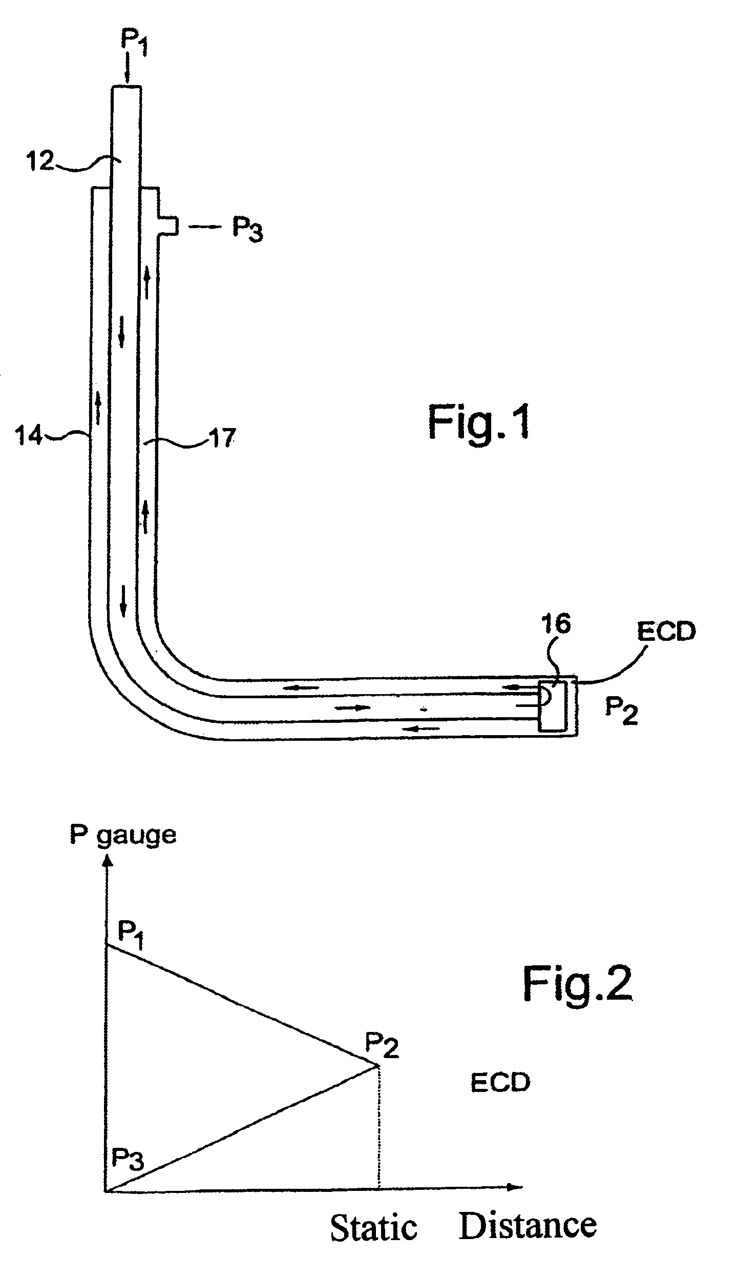
[0033]Reference is first made to FIG. 1 of the drawings, which illustrates a conventional drilling operation. A rotating drill string 12 extends through a borehole 14, and drilling mud is pumped from the surface down the drill string 12, to exit the string via jetting ports (not shown) in a drill bit 16, and returns to the surface via the annulus 17 between the string 14 and the bore hole wall.

[0034]Reference is now also made to FIG. 2 of the drawings, which is a sketch graph of the pressure of the drilling mud at various points in the wellbore 14 as illustrated in FIG. 1. The mud enters the drillstring at the surface at a relatively high pressure P1, and emerges from the bit 16 at a lower pressure P2 reflecting the pressure losses resulting from the passage of the mud through the string 12 and bit 16. The drilling mud returns to the surface via the annulus 17 and reaches surface at close to atmospheric pressure P3.

[0035]FIG. 3 of the drawings illustrates a drilling operation in acc...


PUM


Abstract

A drilling method in which a rotary drill bit is mounted on a tubular drillstring extending through a bore comprises: drilling through a formation containing fluid at a predetermined pressure; circulating drilling fluid down through the drill string to exit the string at or adjacent the bit, and then upwards through an annulus between the string and bore wall; and adding energy to the drilling fluid in the annulus at a location above the formation. The addition of energy to the fluid in the annulus has the effect that the pressure of the drilling fluid above the formation may be higher than the pressure of the drilling fluid in communication with the formation and that predetermined differential may be created between the pressure of the formation fluid and the pressure of the drilling fluid in communication with the formation.

Description

CROSS-REFERENCE TO RELATED APPLICATIONS[0001]This application is a continuation of U.S. Ser. No. 09 / 914,338, filed Jan. 8, 2002, now U.S. Pat. No. 6,719,071, which is the National Stage of International Application No. PCT / GB00 / 00642, filed on Feb. 25, 2000, and published under PCT Article 21(2) in English, and claims priority of United Kingdom Application No. 9904380.4 filed on Feb. 25, 1999. The aforementioned applications are herein incorporated by reference in their entirety.BACKGROUND OF THE INVENTION[0002]1. Field of the Invention[0003]The present invention relates to a drilling method, and to a drilling apparatus. Embodiments of the invention relate to a drilling method and apparatus where the effective circulating density (ECD) of drilling fluid (or drilling “mud”) in communication with a hydrocarbon-bearing formation is lower than would be the case in a conventional drilling operation. The invention also relates to an apparatus for reducing the buildup of drill cuttings or ...

Claims


Application Information

Patent Timeline
Patent Type & Authority Patents(United States)
IPC IPC(8): E21B4/02E21B21/00E21B21/08
CPCE21B4/02E21B21/00E21B21/08E21B2021/006E21B21/085E21B21/10
Inventor MOYES, PETER BARNES
Owner GASOLINEINE WELLSYST
Why Eureka
Try Eureka