Rotary machine sealing assembly

a sealing assembly and rotary machine technology, applied in the direction of machines/engines, stators, liquid fuel engines, etc., can solve the problems of gas or steam leakage out of the gas or steam path or into the gas or steam path, general undesirable, and lowering the efficiency of the gas turbin

Inactive Publication Date: 2005-11-29
GENERAL ELECTRIC CO
View PDF30 Cites 35 Cited by
  • Summary
  • Abstract
  • Description
  • Claims
  • Application Information

AI Technical Summary

Problems solved by technology

Gas or steam leakage, either out of the gas or steam path or into the gas or steam path, from an area of higher pressure to an area of lower pressure, is generally undesirable.
For example, gas path leakage in the turbine or compressor area of a gas turbine, between the rotor of the turbine or compressor and the circumferentially surrounding turbine or compressor casing, will lower the efficiency of the gas turbine leading to increased fuel costs.
Also, steam-path leakage in the turbine area of a steam turbine, between the rotor of the turbine and the circumferentially surrounding casing, will lower the efficiency of the steam turbine leading to increased fuel costs.
Such a sealing assembly, however, requires a trade-off between turbine efficiency and sealing assembly integrity.
Exceeding the desired clearance degrades the efficiency of the turbine engine.
However, under certain circumstances, for example during transient and startup conditions, the rotary component may be displaced from its normal position, causing the rotary and stationary components to interfere.
As a result, the sealing strips rub against the rotary component, potentially damaging the sealing strips.
Thus, in order to maintain the sealing assembly integrity, a larger than desired sealing assembly clearance may be necessary, which in turn reduces the efficiency of the turbine engine.
However, such techniques are expensive to implement and may require replacement of the rotary components in the event of damage to the machined tooth under unpredictable transient behavior.

Method used


Image

  • Rotary machine sealing assembly
  • Rotary machine sealing assembly
  • Rotary machine sealing assembly

Examples


Embodiment Construction

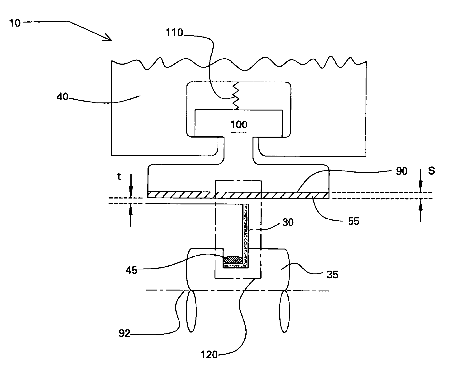
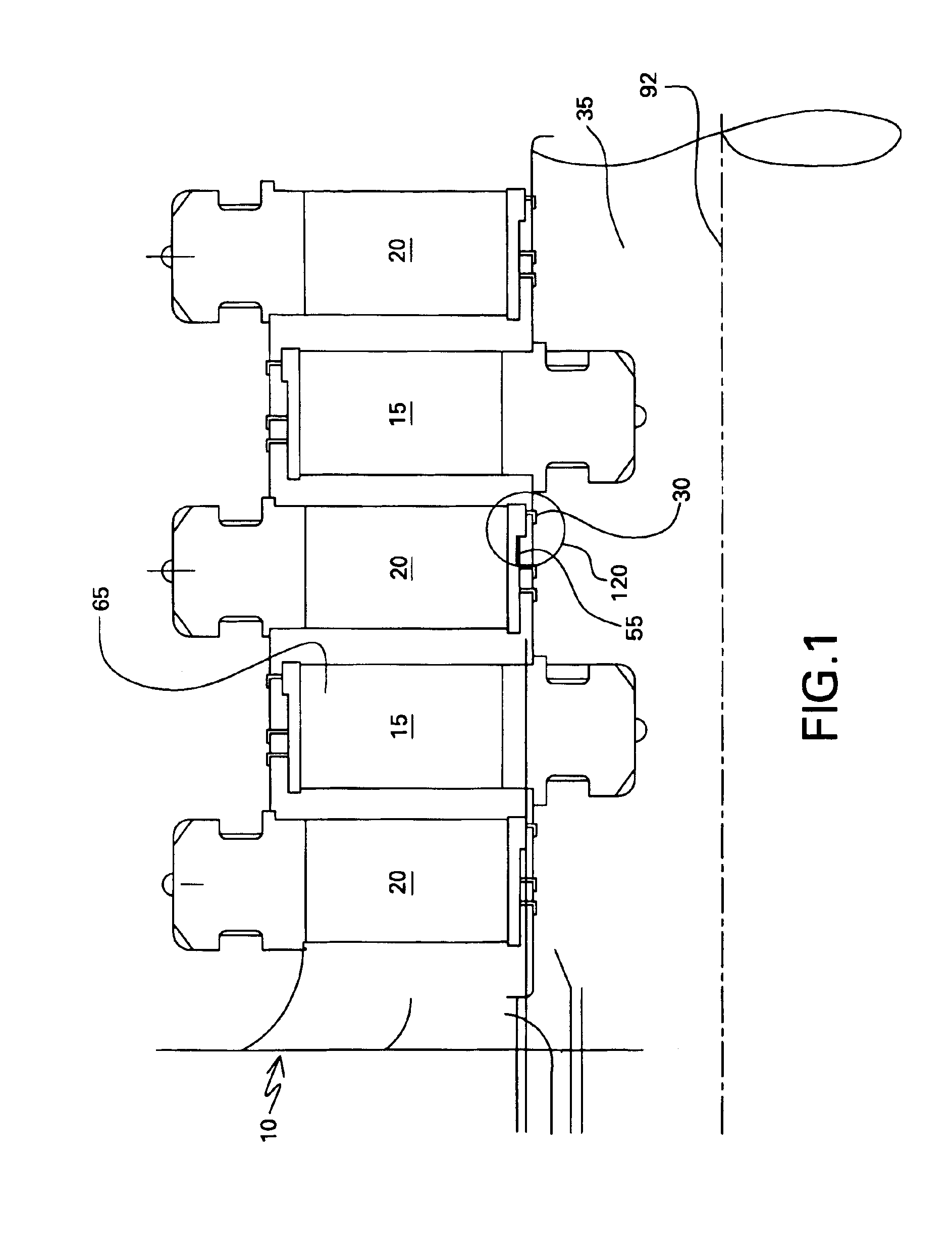
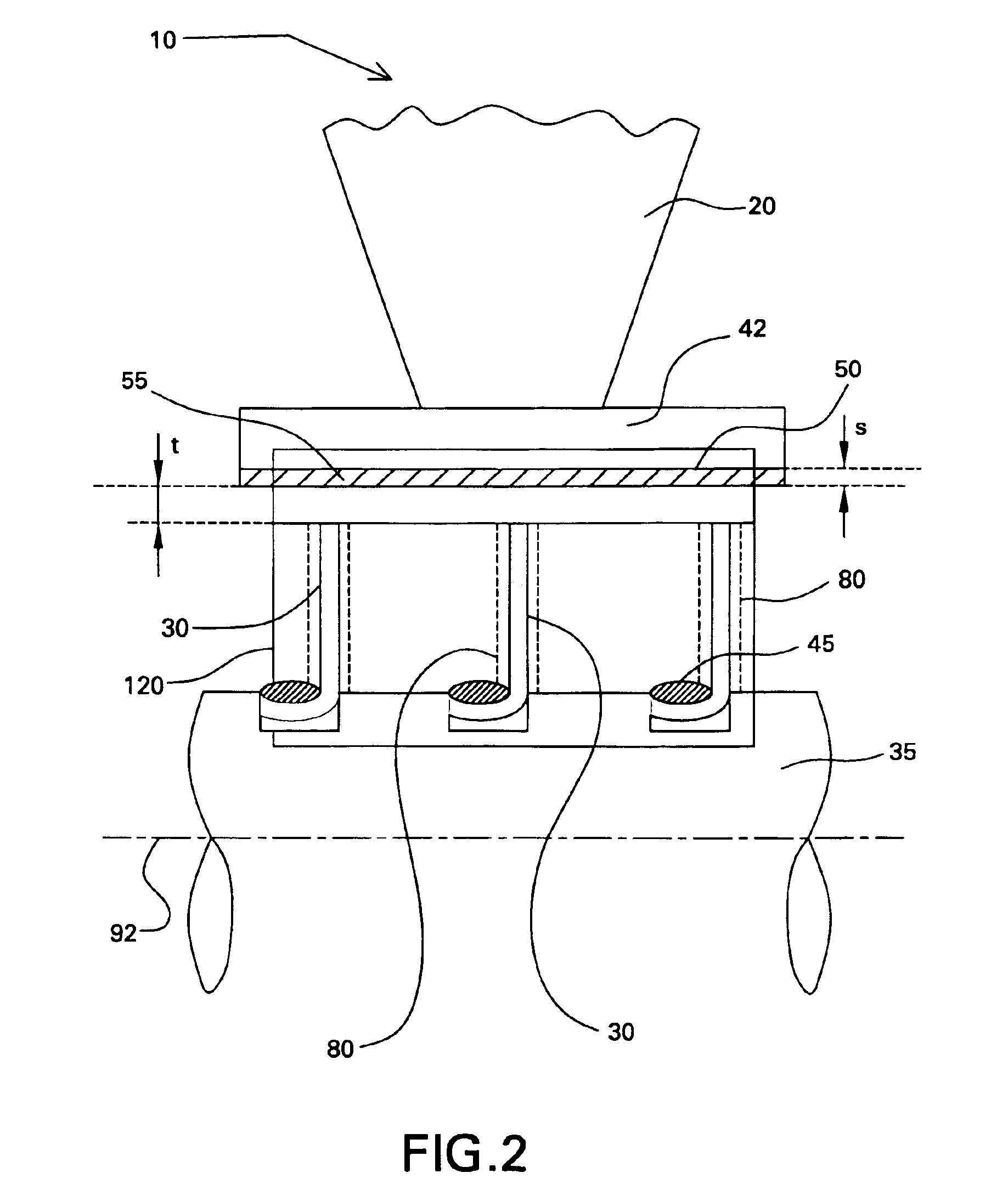
[0011]As illustrated in FIG. 1, a typical rotary machine 10 such as a steam turbine (also indicated by reference numeral 10), typically includes at least one rotary component 15, such as a rotor 35 or rotating buckets 65, and a stationary component 20, such as a stationary steam nozzle (also indicated by reference numeral 20) surrounding the rotary component 15. The rotary component 15 and the stationary components 20 are disposed circumferentially around a common axis 92. For the steam turbine 10, steam passing through the stationary nozzles 20 is directed at a high velocity against the rotary component 15 causing it to rotate at a high speed.

[0012]A sealing assembly 120 is described first with reference to FIG. 1. As shown, the sealing assembly 120 is disposed between the rotary component 15 and the stationary component 20. Referring also to FIG. 1, the sealing assembly 120 includes at least one sealing strip 30, which is affixed to either the rotary component 15 or the stationary...


PUM


Abstract

A sealing assembly for disposition in a rotary machine is disposed between a rotary component and a stationary component of the rotary machine. The sealing assembly includes at least one sealing strip affixed by caulking to one of the rotary and stationary components. An abradable portion is disposed on another of the rotary and stationary components and is positioned radially opposite to the at least one sealing strip. The abradable portion includes a thermal spray coated material, and the thermal spray coated material includes Cobalt, Nickel, Chromium, Aluminum, Yttrium (CoNiCrAlY) and further includes a material selected from the group consisting of hexagonal boron nitride, a thermoset polymer, and combinations thereof.

Description

BACKGROUND OF INVENTION[0001]The present invention relates generally to sealing assemblies for rotary machines and, more particularly, to a sealing assembly for a steam or gas turbine.[0002]Rotary machines include, without limitation, steam turbines, compressors and gas turbines. A steam turbine has a steam path that typically includes, in serial-flow relationship, a steam inlet, a turbine, and a steam outlet. A gas turbine has a gas path, which typically includes, in serial-flow relationship, an air intake (or inlet), a compressor, a combustor, a turbine, and a gas outlet (or exhaust nozzle). Gas or steam leakage, either out of the gas or steam path or into the gas or steam path, from an area of higher pressure to an area of lower pressure, is generally undesirable. For example, gas path leakage in the turbine or compressor area of a gas turbine, between the rotor of the turbine or compressor and the circumferentially surrounding turbine or compressor casing, will lower the efficie...

Claims


Application Information

Patent Timeline
Patent Type & Authority Patents(United States)
IPC IPC(8): F01D11/00F01D11/02F01D11/08F01D11/12F02C7/28F16J15/32F16J15/44
CPCF01D5/225F01D11/001F01D11/025F01D11/12F16J15/3288
Inventor GHASRIPOOR, FARSHADTURNQUIST, NORMAN ARNOLDCOURTURE, BERNARD ARTHURKORZUN, RONALD WAYNE
Owner GENERAL ELECTRIC CO
Why Eureka
Try Eureka