Small separation apparatus

US6969453B2Inactive Publication Date: 2005-11-29NUSEP

Image

  • Small separation apparatus
  • Small separation apparatus
  • Small separation apparatus

Examples


Embodiment Construction

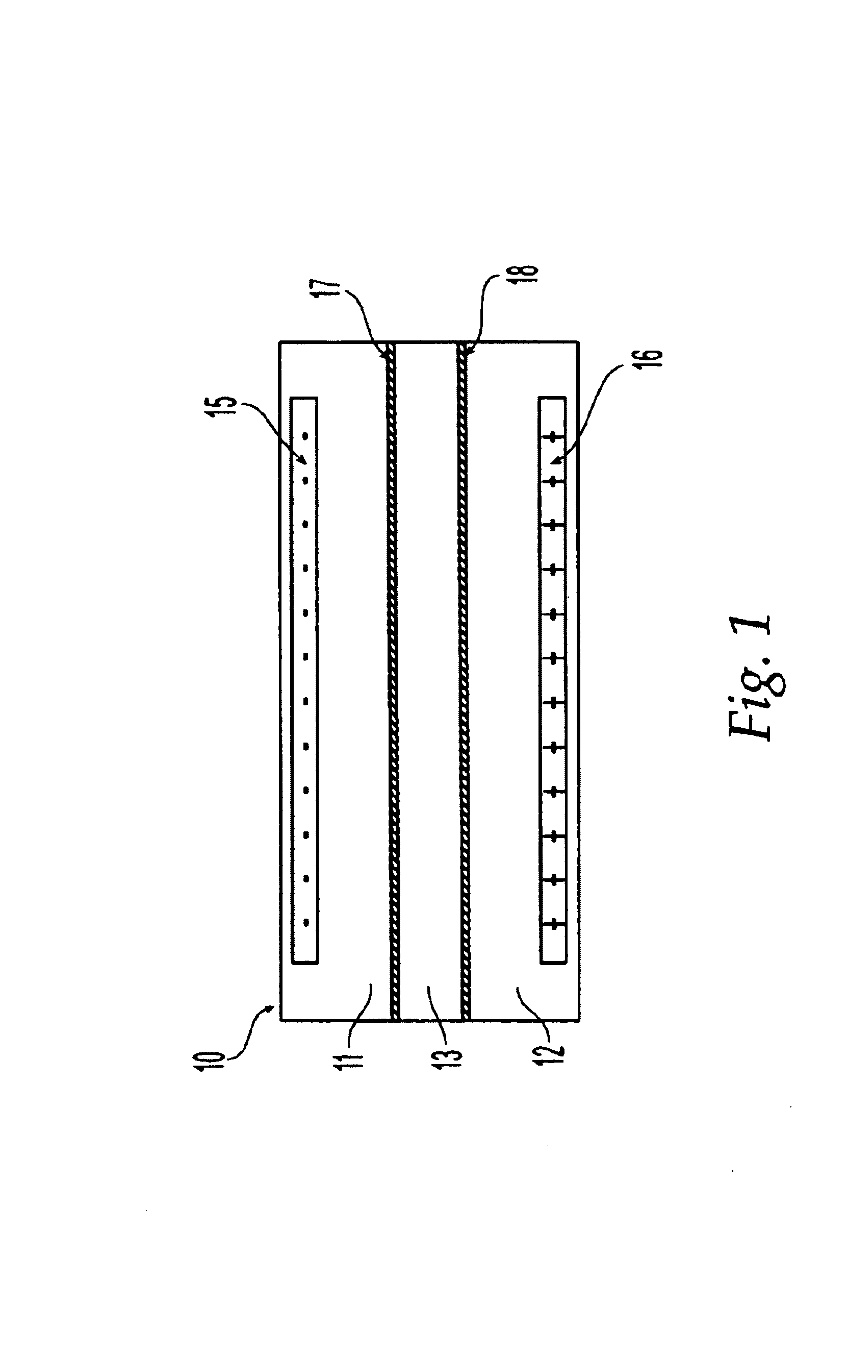
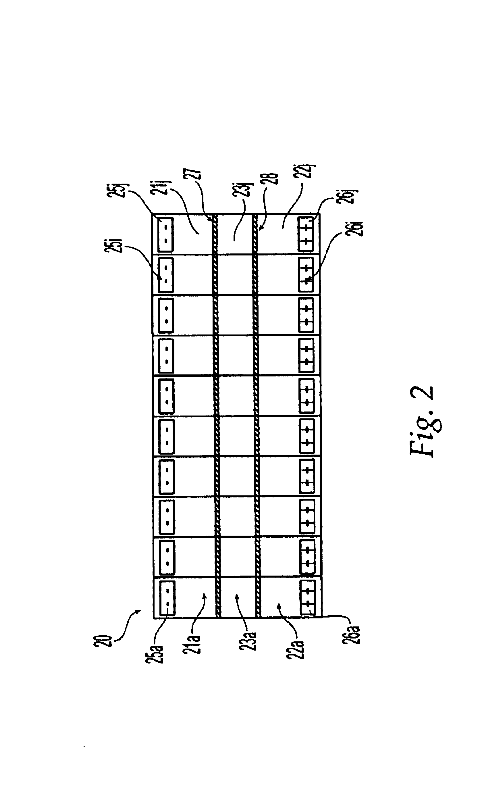
[0041]Before describing the preferred embodiments in detail, the principal of operation of the apparatus will first be described. An electric field applied to charged molecules including macromolecules such as proteins in solution will cause the molecules to move to one of the electrodes. If the compound has a positive charge, it will move to the negative electrode (cathode). Conversely, a negatively-charged compound will move to the positive electrode (anode).

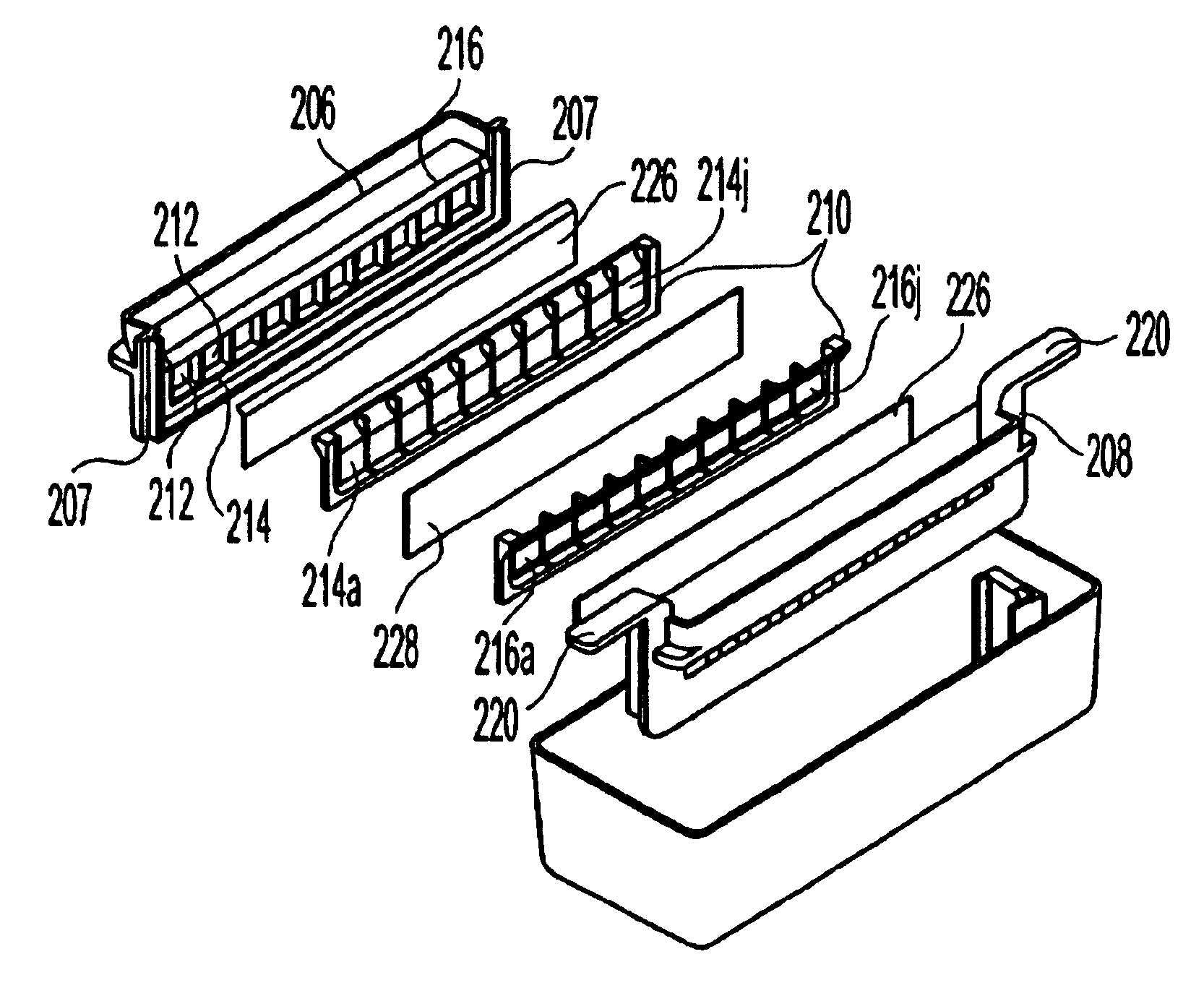
[0042]In the apparatus of the present invention for separating compounds, an electrophoretic separation membrane is placed in an electric field and compounds are selectively transported between the sample and the separation chambers. The particular separation membrane used will vary for different applications and generally has a relatively large, but well defined, pore size. The sample and separation chambers are isolated from the electrodes by two restriction membranes. Depending on the type of restriction membranes used, the...


PUM

PropertyMeasurementUnit
Lengthaaaaaaaaaa
Lengthaaaaaaaaaa
Lengthaaaaaaaaaa

Abstract

An electrophoresis apparatus for processing compounds in small sample volumes comprising a cathode in a static cathode buffer zone or compartment, an anode in a static anode buffer zone or compartment. The cathode disposed relative to the anode so as to be adapted to generate an electric field in an electric field area therebetween upon application of a voltage potential between the cathode and anode. A removable cartridge disposed in the electric field area between the anode and the cathode. The cartridge containing a first non-isoelectric separation barrier and also a second non-isoelectric separation barrier disposed between a selected one of the cathode buffer zone and the anode buffer zone and the first barrier so as to define a first chamber having an interstitial volume of less than 5 ml therebetween.

Description

BACKGROUND OF THE INVENTION[0001]This invention relates to an electrophoretic separation apparatus and in particular, to apparatus for treatment or separation of compounds including macromolecules in small volumes.[0002]In the past, the separation of macromolecular solutes was performed by a process known as electrophoretic separation or electrophoresis, in particular, fixed boundary electrophoretic separation. In fixed boundary electrophoresis, a semi-permeable membrane (hereinafter referred to as a separation membrane), acts to separate two streams of liquid carrying macromolecular solutes such as proteins, known as the sample and the downstream. The streams flow between charged electrodes and at least one macromolecular solute migrates across the membrane from one stream to the other stream under the influence of the electric field. The apparatus also includes flow paths for buffer solutions and further semi-permeable membranes, hereinafter referred to as restriction membranes, d...

Claims


Application Information

Patent Timeline
29 Nov 2005
Publication
US6969453B2
IPC
B01D57/02; B01D61/18; B01D61/28; G01N1/10; B01D61/42; B01D61/46; B01D61/58; B01D71/40; B03C5/00; C07K1/26; C25B7/00; G01N27/26; G01N27/447
CPC
B01D57/02; B01D61/425; G01N27/44773; B01D61/4251
Inventors
OGLE, DAVID; RYLATT, DENNIS