Scouring method

a technology of scouring and scouring plates, applied in the direction of membranes, filtration separation, separation processes, etc., can solve the problems of high efficiency of systems, low production efficiency, and high cost of production, operation and maintenance, and achieve the effect of simple effectiv

Inactive Publication Date: 2005-11-29
EVOQUA WATER TECH LLC
View PDF22 Cites 74 Cited by
  • Summary
  • Abstract
  • Description
  • Claims
  • Application Information

AI Technical Summary

Benefits of technology

[0012]The present invention seeks to overcome or at least ameliorate the problems of the prior art by providing a simple effective system and method for removing fouling materials from the surface of the porous membranes by use of gas bubbles.
[0013]According to one aspect, the present invention provides a method of removing fouling materials from the surface of a plurality of porous membranes arranged in a membrane module, the porous membranes forming an array, the module having a header wherein said membranes are mounted, the header connected to a source of pressurized gas, the method comprising providing, through the header, gas bubbles in a uniform distribution relative to the porous membrane array such that said bubbles move past the surfaces of said membranes to dislodge fouling materials therefrom, said membranes being arranged in close proximity to one another and mounted to prevent excessive movement therebetween. The porous membranes may comprise hollow fibre membranes. Preferably, the fibre membranes are arranged in bundles surrounded by a perforated cage which serves to prevent said excessive movement therebetween.
[0016]According to one preferred form, the present invention provides a method of removing fouling materials from the surface of a plurality of porous hollow fibre membranes mounted and extending longitudinally in an array to form a membrane module, said membranes being arranged in close proximity to one another and mounted to prevent excessive movement therebetween, the method comprising the steps of providing, from within said array, via the header connected to a source of pressurized gas, uniformly distributed gas bubbles, said distribution being such that said bubbles pass substantially uniformly between each membrane in said array to scour the surface of said membranes and remove accumulated solids from within the membrane module.
[0019]Filtrate is normally withdrawn from the fibres by application of suction applied thereto, however, it will be appreciated that any suitable means of providing TMP may be used. A porous sheet may be used in conjunction with the holes or separately to provide a more uniform distribution of gas bubbles. The porous sheet also provides the added advantage of preventing solids ingressing into the air supply plenum chamber.

Problems solved by technology

These systems are highly effective but are also expensive to produce, operate and maintain.
Simpler systems using membrane arrays freely mounted vertically in a tank and using suction applied to the fibre lumens to produce TMP have also been developed, however, these systems have been found in the past to be less effective than the pressurised systems.
This limits the depth of fibre bundle which can be effectively cleaned.
Feed is supplied to the shell while this gas backwash is taking place to cause turbulence and frothing around the membrane walls resulting in further dislodgment of accumulated solids.

Method used


Image

  • Scouring method
  • Scouring method
  • Scouring method

Examples


Embodiment Construction

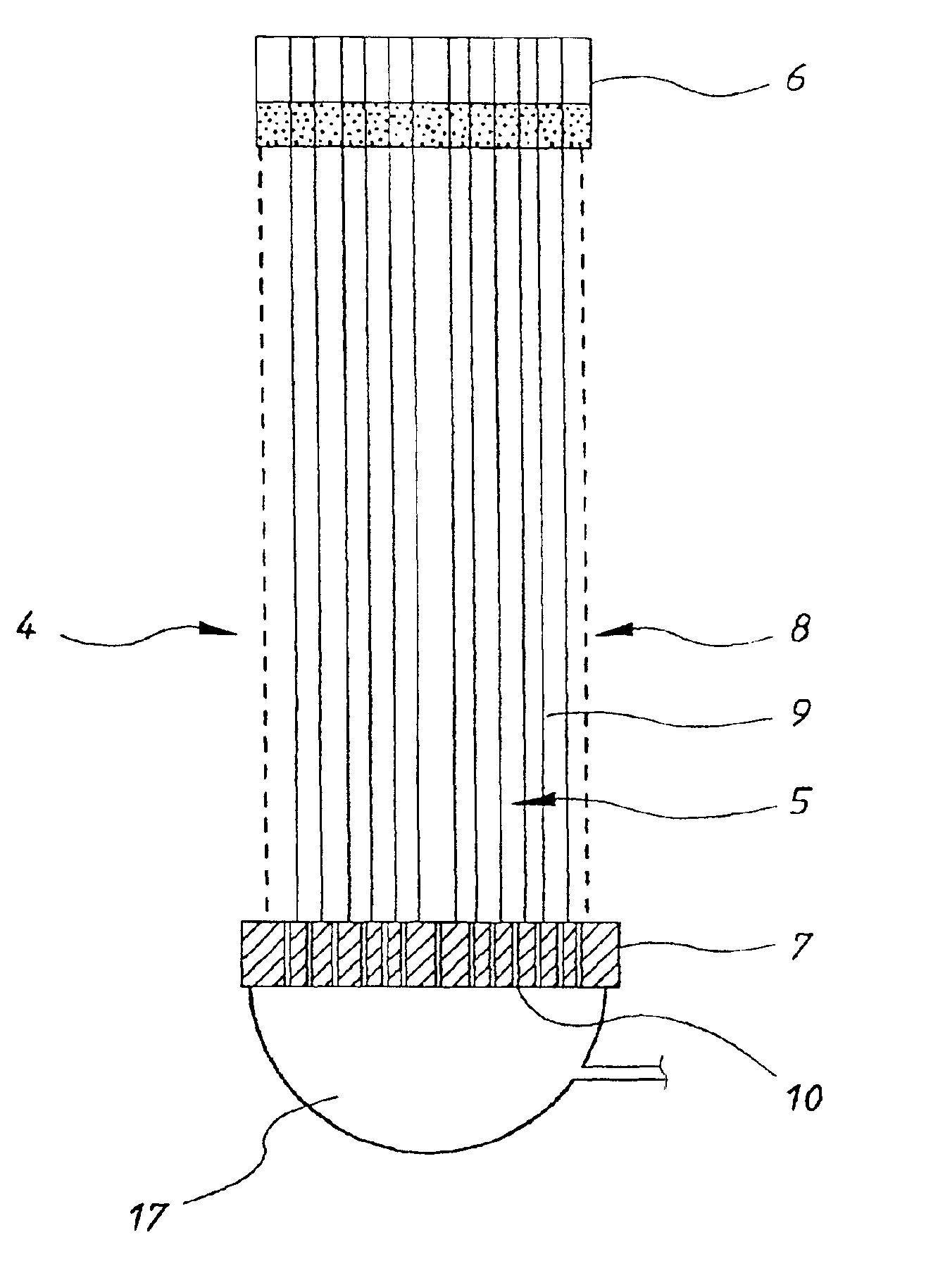
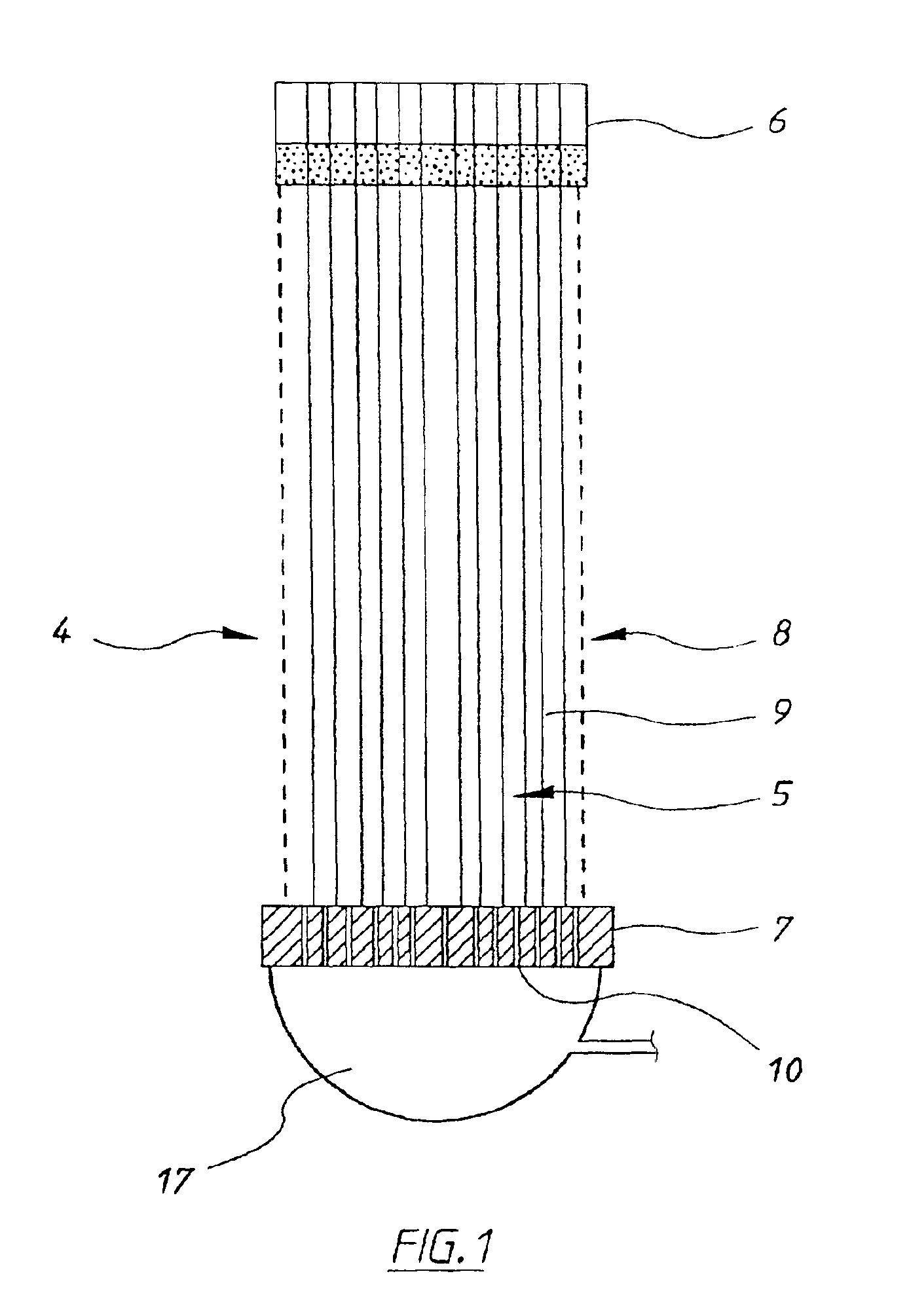
[0043]Referring to FIG. 1, the membrane module 4, according to this embodiment, comprises a cylindrical array or bundle of hollow fibre membranes 5 extending longitudinally between upper and lower potting heads 6, 7. Optionally, a screen or cage 8 surrounds the array 5 and serves to hold the fibres 9 in close proximity to each other and prevent excessive movement. The fibres 9 are open at the upper potting head 6 to allow for filtrate removal from their lumens and sealed at the lower potting head 7. The lower potting head 7 has a number of holes 10 uniformly distributed therein to enable gas / air to be supplied therethrough. The fibres are fixed uniformly within the potting heads 6 and 7 and the holes 10 are formed uniformly relative to each fibre 9 so as to provide, in use, a uniform distribution of gas bubbles between the fibres.

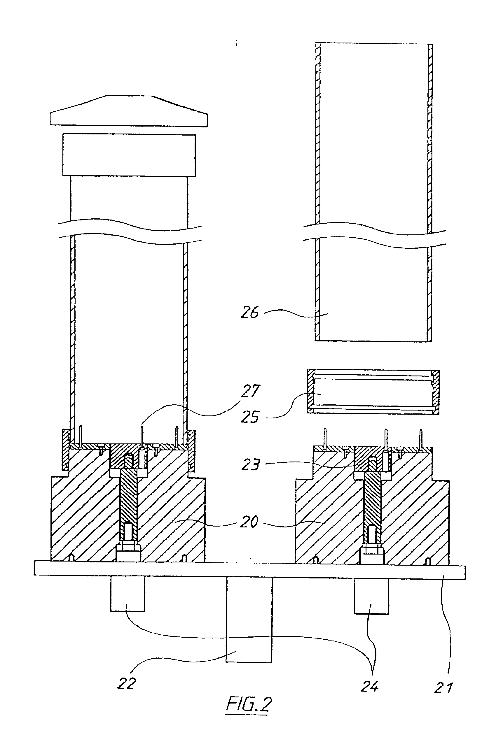
[0044]The holes are formed as part of the potting process as described below. The arrangement of the holes relative to one another as well as the arrangeme...


PUM

PropertyMeasurementUnit
diameteraaaaaaaaaa
sizeaaaaaaaaaa
transmembrane pressuresaaaaaaaaaa

Abstract

A method and apparatus for removing fouling materials from the surface of a plurality of porous membranes (9) arranged in a membrane module (4) by providing, from within the module, by means (10) other than gas passing through the pores of said membranes, gas bubbles in a uniform distribution relative to the porous membrane array such that the bubbles move past the surfaces of the membranes (9) to dislodge fouling materials therefrom. The membranes (9) are arranged in close proximity to one another and mounted to prevent excessive movement therebetween. The bubbles also produce vibration and rubbing together of the membranes to further assist removal of fouling materials.

Description

[0001]This application is a continuation of application Ser. No. 09 / 336,059, filed Jun. 18, 1999 now U.S. Pat. No. 6,555,005, which is the national phase under 35 U.S.C. §371 of prior PCT International Application No. PCT / AU97 / 00855 which has an International filing date of Dec. 18, 1997, which designated the United States of America, and which was published by the International Bureau in English on Jul. 2, 1998.BACKGROUND OF THE INVENTION[0002]1. Technical Field[0003]The present invention relates to the use of a gas bubble system to remove fouling materials from the surface of membranes used in filtration systems and the like.[0004]2. Background Art[0005]A variety of membrane filtration systems are known and many of these use pressurised systems operating at high transmembrane pressures (TMP) to produce effective filtering and high filtrate flux. These systems are highly effective but are also expensive to produce, operate and maintain. Simpler systems using membrane arrays freely ...

Claims


Application Information

Patent Timeline
Patent Type & Authority Patents(United States)
IPC IPC(8): B01D61/18B01D61/20B01D63/00B01D63/02B01D63/16B01D65/02B01D65/08
CPCB01D61/18B01D63/022B01D63/024B01D63/16B01D65/02B01D65/08B01D2315/06B01D2321/04B01D2321/16B01D2321/168B01D2321/185B01D2321/2058
Inventor ZHA, FUFANGKOPP, CLINTON V.MCMAHON, ROBERT J.JOHNSON, WARREN T.BECK, THOMAS W.
Owner EVOQUA WATER TECH LLC
Why Eureka
Try Eureka