Mechanism for converting mechanical energy for wind powered energy systems

a technology of wind power energy and mechanical energy, applied in the direction of machines/engines, electric generator control, sustainable manufacturing/processing, etc., can solve the problems of waste of valuable energy and not all, and achieve the effect of improving the efficiency of the power cycle and increasing the amount of energy

Inactive Publication Date: 2005-11-29
CONLON THOMAS R
View PDF5 Cites 6 Cited by
  • Summary
  • Abstract
  • Description
  • Claims
  • Application Information

AI Technical Summary

Benefits of technology

[0009]The improved drive mechanism for a windmill improves the efficiency of the power cycle by transitioning to the full upstroke with only a minimal dwell on either end of the stroke for transition to movement in the opposite direction. Wind movement causes a wind wheel to rotate a shaft which drives dual drive chains into movement. The drive chain sprockets are coupled to two force chain sprockets which drive two force chains. A chain pin is coupled at one position to the force chains and also coupled to a captive slide. A pump rod is connected to the slide and driven an equal distance in each direction by the driven slide. Full mechanical force can thus be applied equally on both the full upstroke and the full downstroke. The result is the ability to put to useful work a significantly higher amount of energy on the upstroke and the full mechanical force on the downstroke as well. A high reliability oil bucket chain link lubrication system is used to flood the entire chain mechanism with abundant oil to avoid the problems in traditional pumps of loss of priming, seal wear, etc.

Problems solved by technology

t all. Much useful energy is wasted as a result of these defici

Method used


Image

  • Mechanism for converting mechanical energy for wind powered energy systems
  • Mechanism for converting mechanical energy for wind powered energy systems
  • Mechanism for converting mechanical energy for wind powered energy systems

Examples


Embodiment Construction

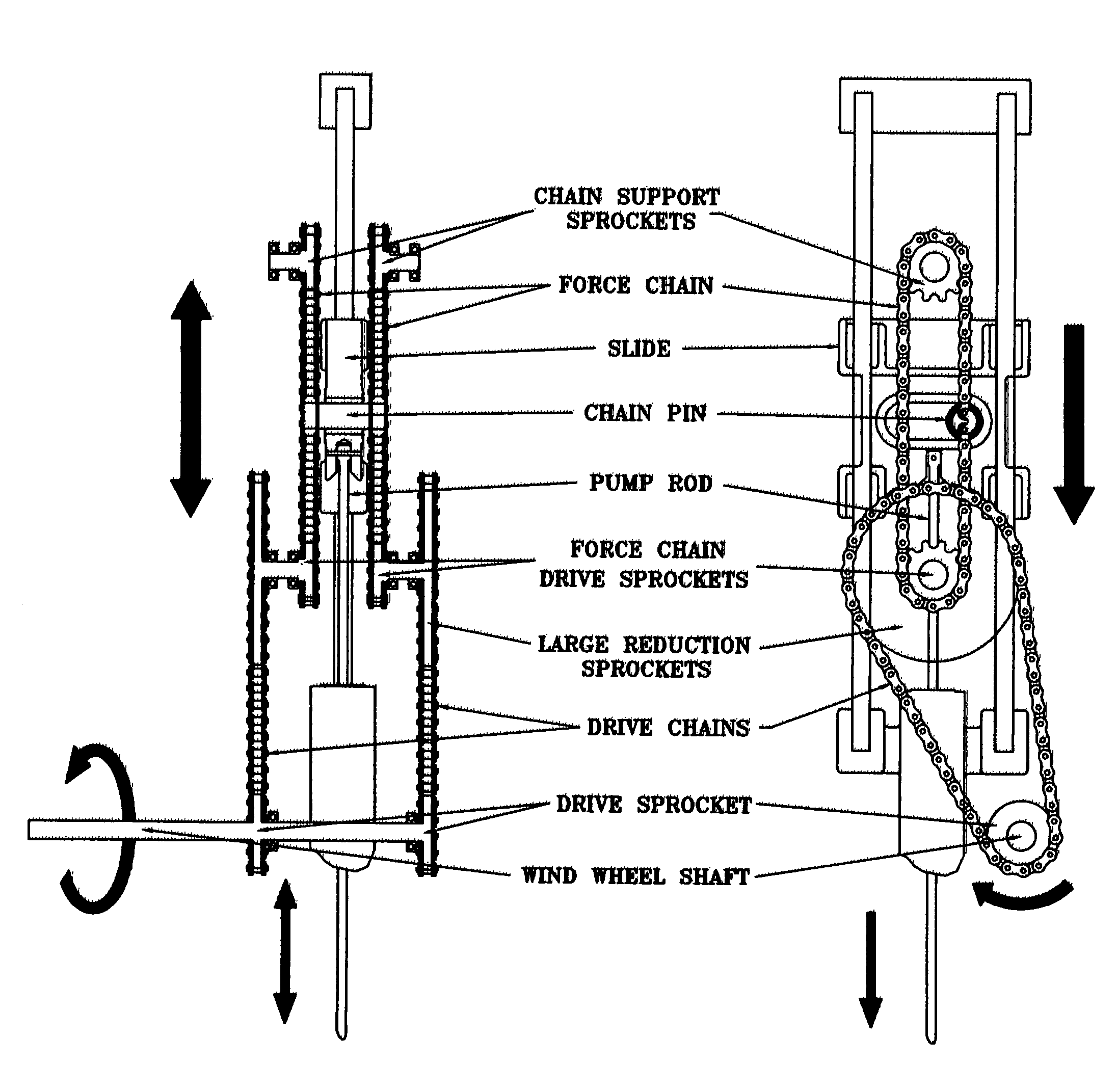
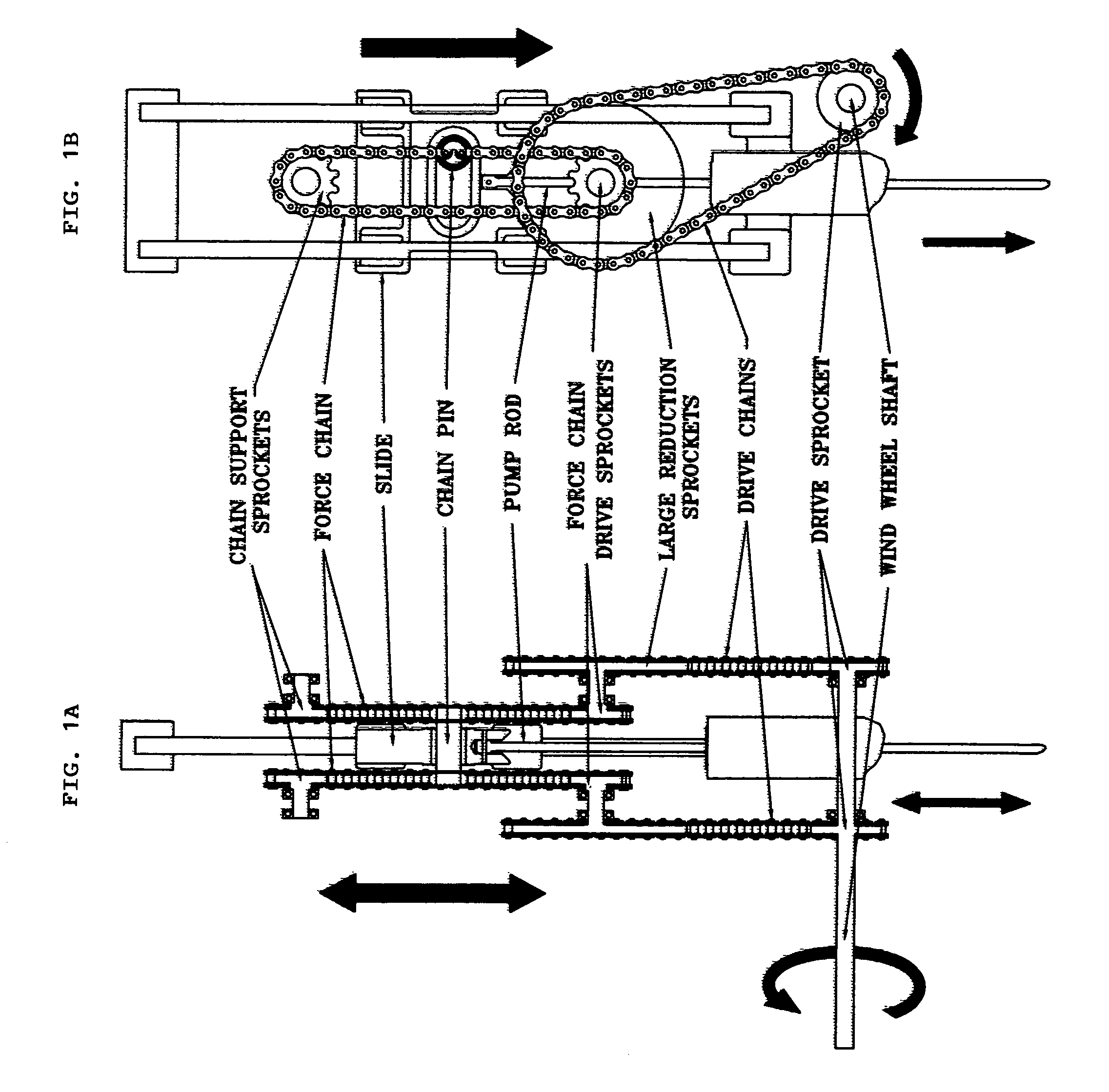
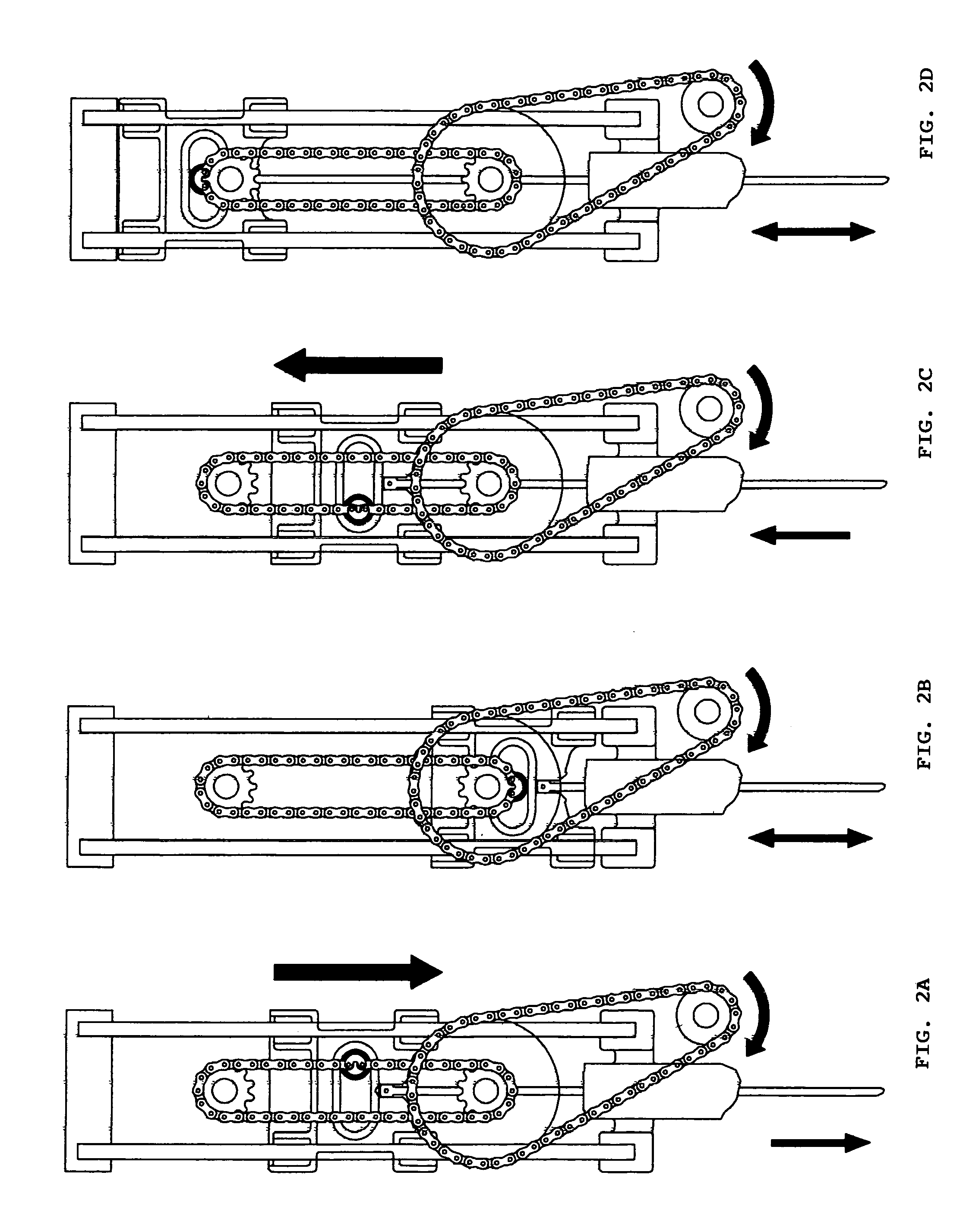
[0014]The overall purpose of this invention is to increase the amount of liquid or gas pumped or otherwise to increase the amount of work performed by the common windmill. The improved drive mechanism presented herein improves the efficiency of the power cycle by transitioning to the full upstroke with only a minimal dwell on either end of the stroke for transition to movement in the opposite direction. Additionally, full mechanical force can be applied equally on both the full upstroke and the full down stroke. The result is the ability to put to useful work a significantly higher amount of energy on the up stroke and an equally important advantage of being able to provide full mechanical force on the down stroke as well. This is not possible with the traditional windmill gearbox design. Ultimately, more work can be performed and with the inherent balance of forces applicable by this design, more useful work can be done at lower wind speeds than by the designs currently in use.

[001...


PUM


Abstract

An improved drive mechanism for a windmill has: (a) a drive chain driven into movement by a wind wheel shaft driven into rotation by wind movement against a wind wheel; (b) a drive chain sprocket driven by the drive chain and coupled to a force chain sprocket to correspondingly drive a force chain; (c) a chain pin coupled at one position to the force chain and also coupled to a captive slide; and (d) a pump rod connected to the slide and driven an equal distance in each direction by the driven slide in order to convert full mechanical force equally on both the full upstroke and the full downstroke of the pump rod. The improved drive mechanism improves the efficiency of the power cycle by transitioning to the full upstroke with only a minimal dwell on either end of the stroke for transition to movement in the opposite direction. Full mechanical force can thus be applied equally on both the full upstroke and the full downstroke. A high reliability oil bucket chain link lubrication system is used to flood the entire chain mechanism with abundant oil to avoid the problems in traditional pumps of loss of priming, seal wear, etc.

Description

[0001]This U.S. patent application claims the priority of U.S. Provisional Application No. 60 / 476,118 filed on Jun. 4, 2003, of the same title, and by the same inventor.TECHNICAL FIELD[0002]This invention generally relates to an improvement in the drive mechanism for increasing the amount of work performed by the common windmill.BACKGROUND OF INVENTION[0003]The traditional windmill uses a gear and crank drive that allows for efficient pumping only when the crank is moving in the upward, or lifting direction. Such a pumping system is commonly known as a pump jack. This design allows minimal if any work to be done when the crank is returning to it's starting point at the bottom of the stroke, the only pumping being done at this time is by the displacement of the pump rod, which is usually, minimal. Additionally, the amount of work is significantly reduced at both the beginning of the upward stroke and the last portion of the upward stroke as the crank is nearing or departing from top ...

Claims


Application Information

Patent Timeline
Patent Type & Authority Patents(United States)
IPC IPC(8): B62M1/00F03D9/00F03D11/02H02P9/04
CPCF03D9/001F03D11/024Y02E10/722F03D9/28F03D15/10Y02E10/70Y02E10/72Y02P80/10F03D5/02
Inventor CONLON, THOMAS R.
Owner CONLON THOMAS R
Why Eureka
Try Eureka