One-core two-way optical transmission system

a transmission system and optical transmission technology, applied in the field of onefiber bidirectional optical transmission system, can solve the problems of deterioration of frequency-multiplexed signal, system likely to be affected by four wave mixing, etc., and achieve the effect of high transmission quality

Inactive Publication Date: 2005-11-29
MITSUBISHI ELECTRIC CORP
View PDF11 Cites 12 Cited by
  • Summary
  • Abstract
  • Description
  • Claims
  • Application Information

AI Technical Summary

Benefits of technology

[0040]According to this aspect, since the one-fiber bidirectional optical transmission system is a relay transmission system, signal light transmission with high transmission quality is performed, without being affected by four wave mixing between the signal light and the pump light.

Problems solved by technology

In the one-fiber bidirectional optical transmission system, however, multiplexed signal lights are transmitted bidirectionally, and a plurality of pump lights is used, and hence there is a problem in that the system is likely to be affected by four wave mixing.
As shown in FIG. 10(b), the signal level is raised at a wavelength in the vicinity of 1589 nanometers, thereby causing deterioration in the frequency-multiplexed signal.

Method used


Image

  • One-core two-way optical transmission system
  • One-core two-way optical transmission system
  • One-core two-way optical transmission system

Examples


first embodiment

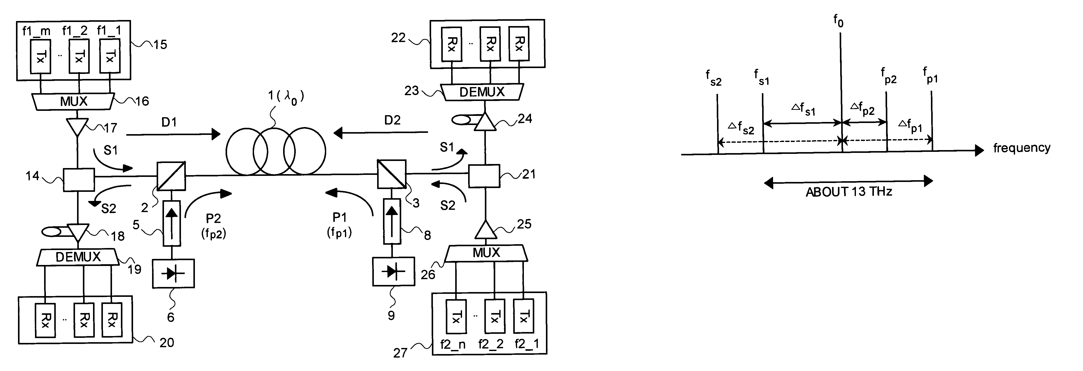
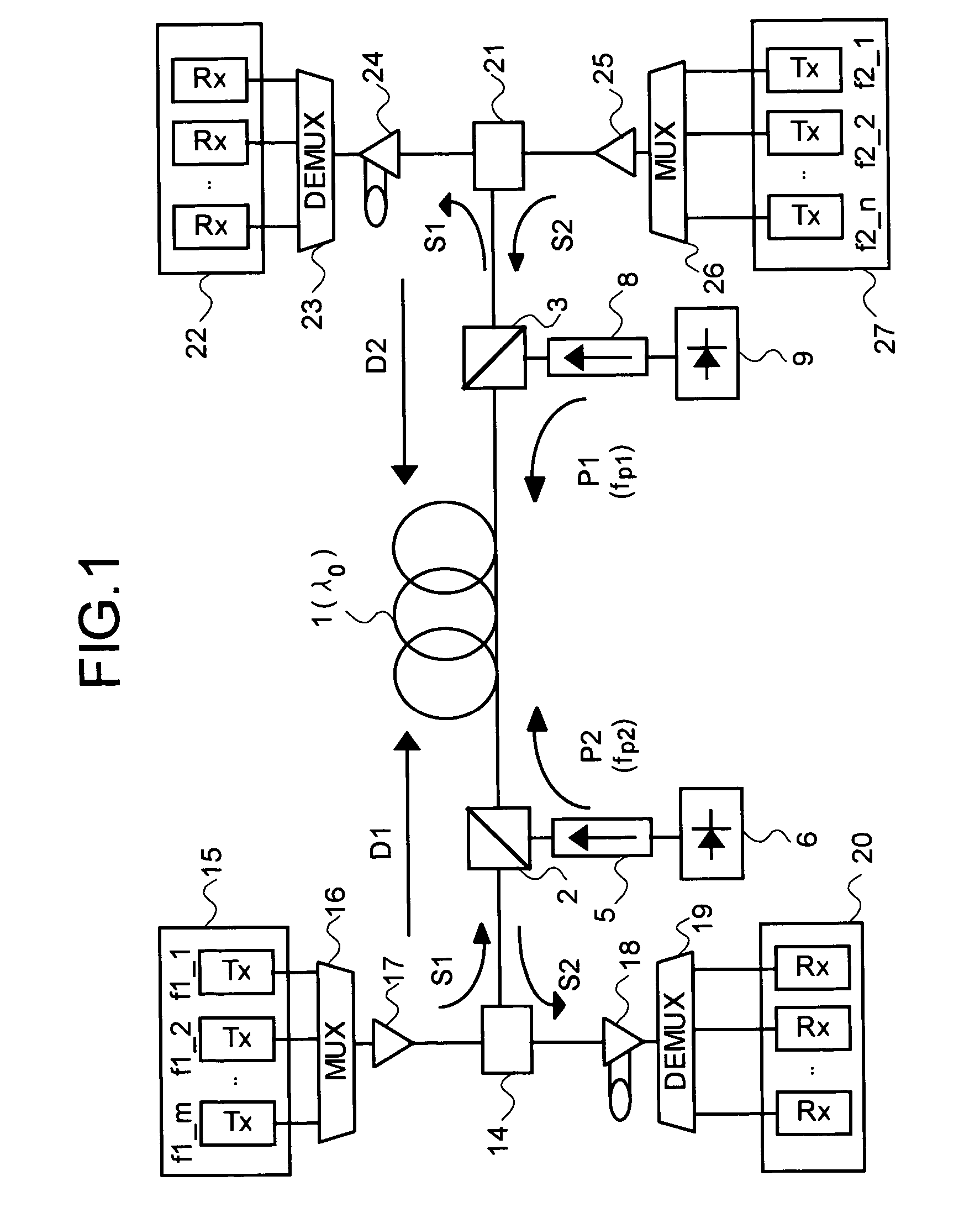
[0053]FIG. 1 is a schematic diagram of the one-fiber bidirectional optical transmission system according to a first embodiment of the present invention. A frequency-selective optical coupler 2 and a frequency-selective optical coupler 3 are respectively connected to one input-output terminal and the other input-output terminal of an operation transmission line 1. To the optical coupler 2 are connected an optical coupler 14 and an optical isolator 5. To the optical isolator 5 is connected a Raman pump source 6. A second Raman pump light P2 generated by the Raman pump source 6 is injected into the optical coupler 2 via the optical isolator 5.

[0054]An optical transmitter 15 includes a plurality of transmitters Tx1—1 to Tx1—m, and these transmitters Tx1—1 to Tx1—m respectively generate signal lights of different frequencies (f1—1 to f1—m). A frequency band where the signal lights are generated is, for example, a frequency band of from 191.6 terahertz to 195.9 terahertz (wavebands of fro...

second embodiment

[0073]FIG. 3 is a schematic diagram of the one-fiber bidirectional optical transmission system according to a second embodiment of the present invention. In the first embodiment, the first signal light S1 and the second signal light S2 respectively have a single frequency. In the second embodiment, however, the first signal light S1 and the second signal light S2 are respectively frequency-multiplexed signal lights. The pumping method is the backward pumping method as in the first embodiment.

[0074]In FIG. 3, the first frequency-multiplexed signal lights S1 are input to the input-output terminal 4, and the second frequency-multiplexed signal lights S2 are input to the input-output terminal 7. The other configuration is the same as that shown in FIG. 1.

[0075]The first Raman pump light P1 generated by the Raman pump source 9 is a pump light of a predetermined frequency, wherein a Raman gain band capable of Raman amplification includes frequency bands of the first frequency-multiplexed ...

third embodiment

[0078]FIG. 5 is a schematic diagram of the one-fiber bidirectional optical transmission system according to the third embodiment. In the third embodiment, a plurality of Raman pump lights is used instead of the Raman pump light of a single frequency in the second embodiment shown in FIG. 3.

[0079]In FIG. 5, Raman pump sources 6 and 9 that generate Raman pump lights of a plurality of frequencies are provided instead of the Raman pump sources 6 and 9 that generate a single Raman pump light, in the configuration shown in FIG. 3. Accompanying this, frequency couplers 10 and 11 are respectively provided between the Raman pump sources 6 and 9 and the optical isolators 5 and 8. The other configuration is the same as that shown in FIG. 3, and hence a part relating to the third embodiment will be mainly explained here.

[0080]A plurality of Raman pump sources 9-1, . . . , 9-r equipped in a Raman pump source section 9 generate Raman pump lights having frequencies different from each other. The R...


PUM

PropertyMeasurementUnit
zero dispersion wavelengthaaaaaaaaaa

Abstract

In a one-fiber bidirectional optical transmission system in which output optical signals of optical transmitter-receivers respectively connected to the opposite ends of one optical fiber transmission line are bidirectionally transmitted in the optical fiber transmission line, which utilizes a Raman amplification effect by backward pumping, a frequency satisfying the conditions of |fs1−f0|≠|fp2−f0| and |fs2−f0|≠|fp1−f0| is selected, where f0 is a zero dispersion frequency of the optical fiber transmission line, fs1 and fs2 are the frequencies of the first signal and the second signal, respectively, and fp1 and fp2 are frequencies of the first Raman pump light and the second Raman pump light, respectively.

Description

[0001]This application is the national phase under 35 U.S.C. §371 of PCT International Application No. PCT / JP03 / 02115 which has an International filing date of Feb. 26, 2003, which designated the United States of America.TECHNICAL FIELD[0002]The present invention relates to a one-fiber bidirectional optical transmission system utilizing a Raman amplification effect.BACKGROUND ART[0003]There are demands in the optical transmission system for an increase in communication capacity, a reduction in communication cost, an increase in transmission speed, and extension of relay intervals, due to a rapid increase in the number of subscribers for the Internet portable telephones and the like, and an increase in needs for speech communication, image communication and the like.[0004]There is a one-fiber bidirectional optical transmission system for realizing these. This system can transmit output light signals from optical transmitter-receivers, respectively connected to the opposite ends of on...

Claims


Application Information

Patent Timeline
Patent Type & Authority Patents(United States)
IPC IPC(8): G02F1/35H01S3/10H01S3/30H04B10/00H04B10/2563H04J14/00H04J14/02
CPCH04B10/2503H04B10/2916H04B10/2971H04B10/2589
Inventor KAJIYA, SATOSHIKINJO, KAORUMIZUOCHI, TAKASHI
Owner MITSUBISHI ELECTRIC CORP
Why Eureka
Try Eureka