Vehicle speed control system and program

Active Publication Date: 2005-11-29
DENSO CORP
View PDF10 Cites 37 Cited by
  • Summary
  • Abstract
  • Description
  • Claims
  • Application Information

AI Technical Summary

Benefits of technology

[0025]As described above, a stable running speed calculating system for a vehicle according to the present invention corrects the reference node angle so that the locus drawn on the basis of the preceding segment and the reference segment approaches a substantially arcuate locus along which the actual vehicle runs. The system further calculates the stable running speed on the ba

Problems solved by technology

Furthermore, when a vehicle runs behind another vehicle, the following vehicle may excessively approach to the preceding vehicle if the preceding vehicle is decelerated to the vehicle speed at which the preceding vehicle can safely pass

Method used


Image

  • Vehicle speed control system and program
  • Vehicle speed control system and program
  • Vehicle speed control system and program

Examples


first embodiment

[First Embodiment]

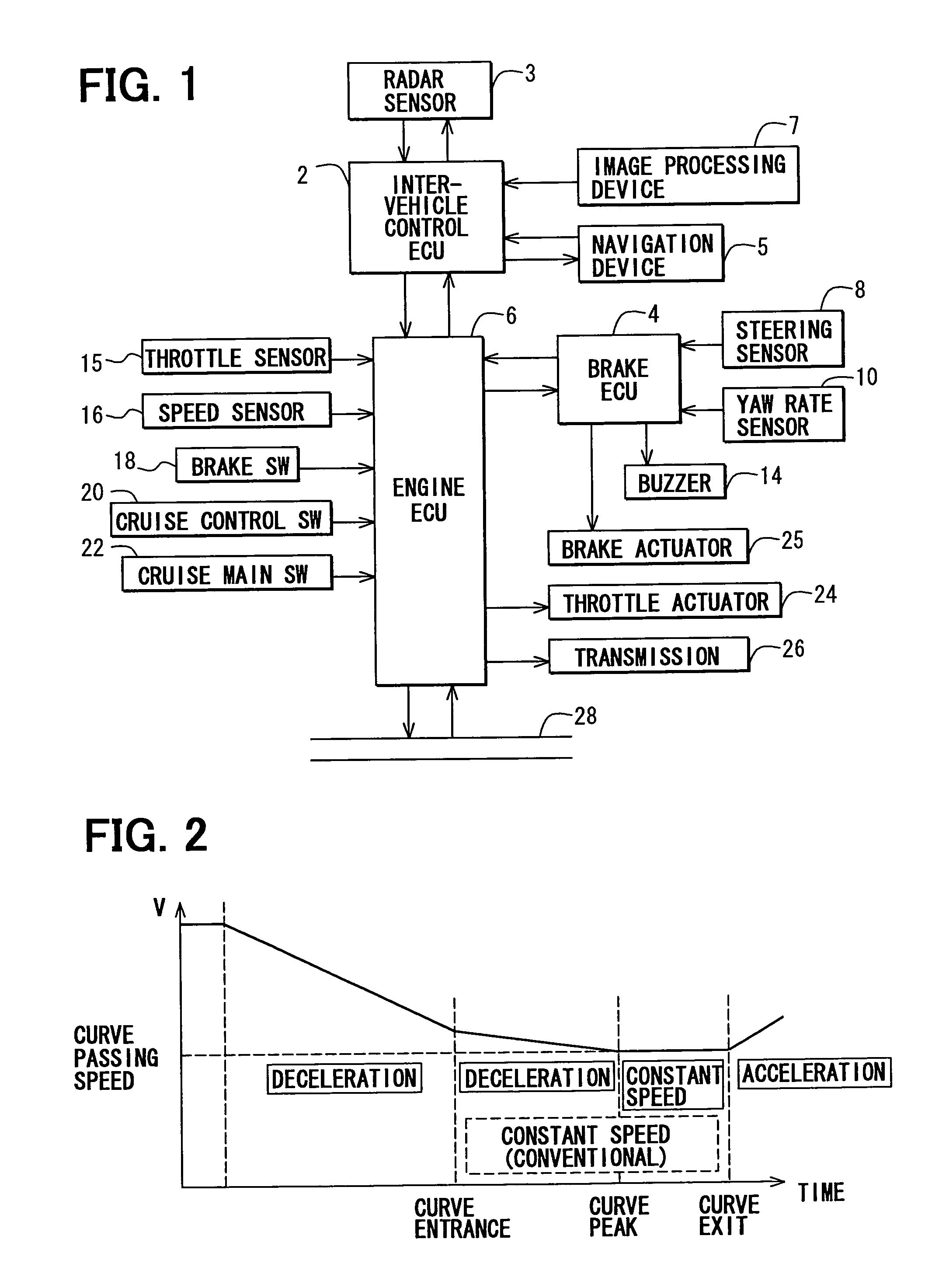
[0046]Referring first to FIG. 1, a cruise control system is shown as a vehicle speed control system. The vehicle speed control system mainly comprises an electric control unit 2 for inter-vehicle control (inter-vehicle control ECU), an electric control unit 6 for engine control (engine ECU) 6 and a brake electric control unit 4 (brake ECU) 4.

[0047]The inter-vehicle control ECU 2 is an electronic circuit which mainly comprises a microcomputer, and receives a current vehicle speed (Vn) signal, a steering angle signal, a yaw rate signal, a target inter-vehicle time signal, wiper switch information, a control status signal for idle control, brake control, etc. from the engine ECU 6. The inter-vehicle control ECU 2 also receives travel route information from a navigation device 5 described later. Furthermore, the inter-vehicle control ECU 2 carries out estimation of the radius of curvature R for a curve, an inter-vehicle control operation, calculation of a stable runnin...

second embodiment

[Second Embodiment]

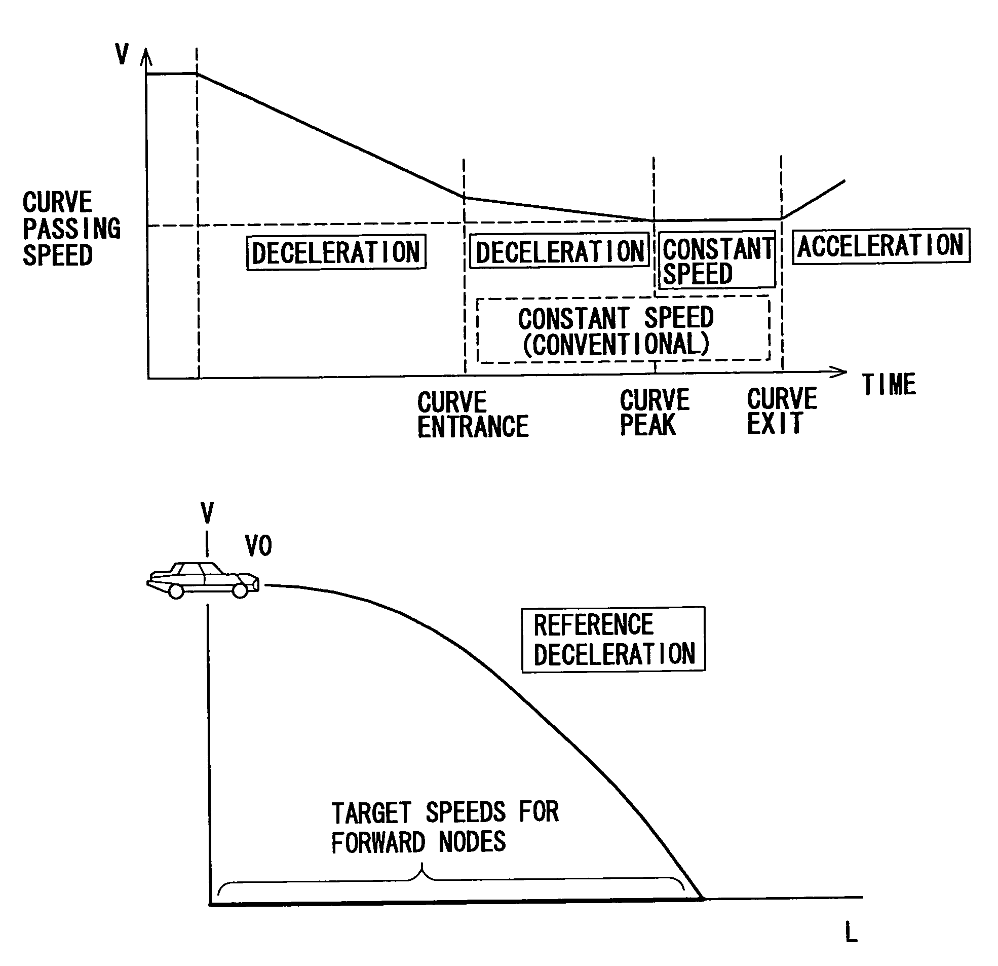
[0111]Next, a second embodiment according to the present invention will be described. As shown in FIG. 11, the vehicle speed control system according to the second embodiment is designed substantially in the same construction as the first embodiment (FIG. 1).

[0112]In the second embodiment, the navigation device 5 detects information of nodes located ahead of the vehicle, and outputs the node information to the inter-vehicle control ECU 2 at a fixed time interval. Specifically, the navigation device 5 calculates the position of the vehicle, and the vehicle speed sensor of the engine ECU 6 described later detects the current vehicle speed. Subsequently, by using the following equation (I), the navigation device 5 calculates the vehicle stop distance Lo from the position of the vehicle to a point at which the vehicle will be stopped when the vehicle is decelerated at the reference deceleration αo.

L0=Vot−αot2 / 2=Vo2 / (2×0.784)  (I)

[0113]Lo: vehicle stop distance (m)

[011...


PUM


Abstract

In a vehicle speed control system, each node existing ahead of a vehicle is detected, and a stable running speed at which the vehicle runs stably when the vehicle passes over each node, and a deceleration needed to accelerate/decelerate the vehicle so that the vehicle speed becomes the stable running speed at each node by the time when the vehicle arrives at the node are successively calculated. On the basis of the deceleration at each node, a point at which the maximum deceleration value is achieved is selected, and the vehicle is subjected to deceleration control so that the vehicle speed becomes the stable running speed at the point. When a point at which the curve degree is maximum is different from a point at which the deceleration value is maximum and also the point is located ahead of the vehicle, further necessary deceleration control is carried out.

Description

CROSS REFERENCE TO RELATED APPLICATION[0001]This application is related to and incorporates herein by reference Japanese Patent Applications No. 2002-340877 filed on Nov. 25, 2002 and No. 2002-342462 filed on Nov. 26, 2002.FIELD OF THE INVENTION[0002]The present invention relates to a system for estimating a stable running speed of a vehicle to control the driving speed of the vehicle so that the vehicle can stably pass over curves, etc. of roads.BACKGROUND OF THE INVENTION[0003]For reducing an operation load imposed on a driver, a vehicle speed control system is known. This system carries out a constant speed driving control operation under which a driver can drive a vehicle with keeping a vehicle speed set by the driver under such a condition that the vehicle speed must be kept to a constant speed, for example, when the vehicle runs on an express highway or the like. The constant speed driving control operation means a control operation for driving a vehicle with keeping a set veh...

Claims


Application Information

Patent Timeline
IPC IPC(8): B60K31/00B60K31/04
CPCB60K31/0058B60K31/04B60W2720/106
Inventor KAGAWA, MASAKAZUTAMAOKI, FUMIHIROISOGAI, AKIRA
Owner DENSO CORP
Why Eureka
Try Eureka