Method of manufacturing diesel fuel

a technology of diesel fuel and manufacturing method, which is applied in the direction of fuels, naphtha treatment, hydrocarbon oil treatment products, etc., can solve the problems of insufficient low temperature performance of the ft middle fraction, and achieve the effects of reducing the boiling range, increasing the production in manufacturing, and being easy to predi

Inactive Publication Date: 2010-12-02
JAPAN OIL GAS & METALS NAT CORP +5
View PDF5 Cites 24 Cited by
  • Summary
  • Abstract
  • Description
  • Claims
  • Application Information

AI Technical Summary

Benefits of technology

[0017]According to the present invention, while fractionating in the second fractionator, a plurality of middle fractions, which have a narrower boiling range and whose PP and kinematic viscosity are easily predictable, are first obtained, and then, the fractions are mixed at a predetermined ratio. Therefore, both the kinematic viscosity and the PP easily fall within their respective standard range (standard ranges corresponding to HS No. 2 gas oil where the kinematic viscosity at 30° C. is 2.5 mm2 / s or more, and the PP is −7.5° C. or below). The facilities required for the present invention may be costly. However, a diesel fuel whose kinematic viscosity and PP simultaneously fall within the respective standard ranges can be certainly obtained without repetition of operation control by trial and error. Therefore, in fact, the present invention is a cost-effective method.
[0018]As a result, it is possible to achieve increased production in manufacturing a diesel fuel from FT synthetic oil while excellent low temperature properties can be achieved.

Problems solved by technology

There is a concern that the FT middle fraction has insufficient low temperature-performance if the fraction is not processed because the FT middle fraction contains a great quantity of n-paraffins.

Method used


Image

  • Method of manufacturing diesel fuel
  • Method of manufacturing diesel fuel

Examples


example 1

Manufacture of Diesel Fuel

(Fractionation of FT Synthetic Oil)

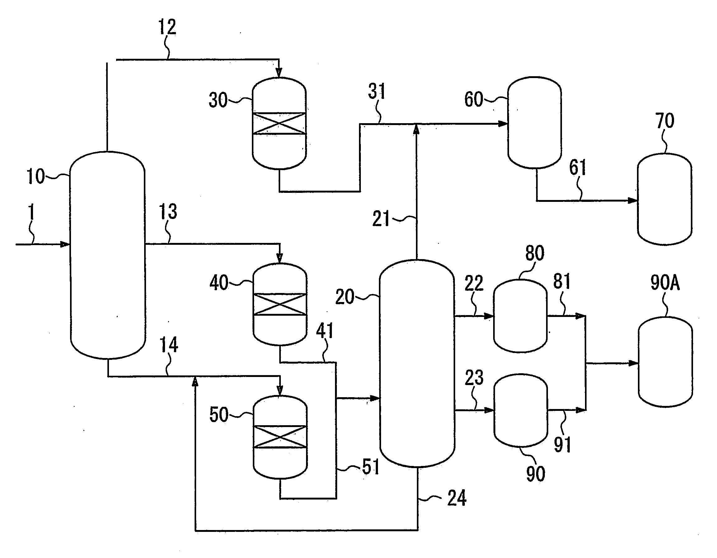
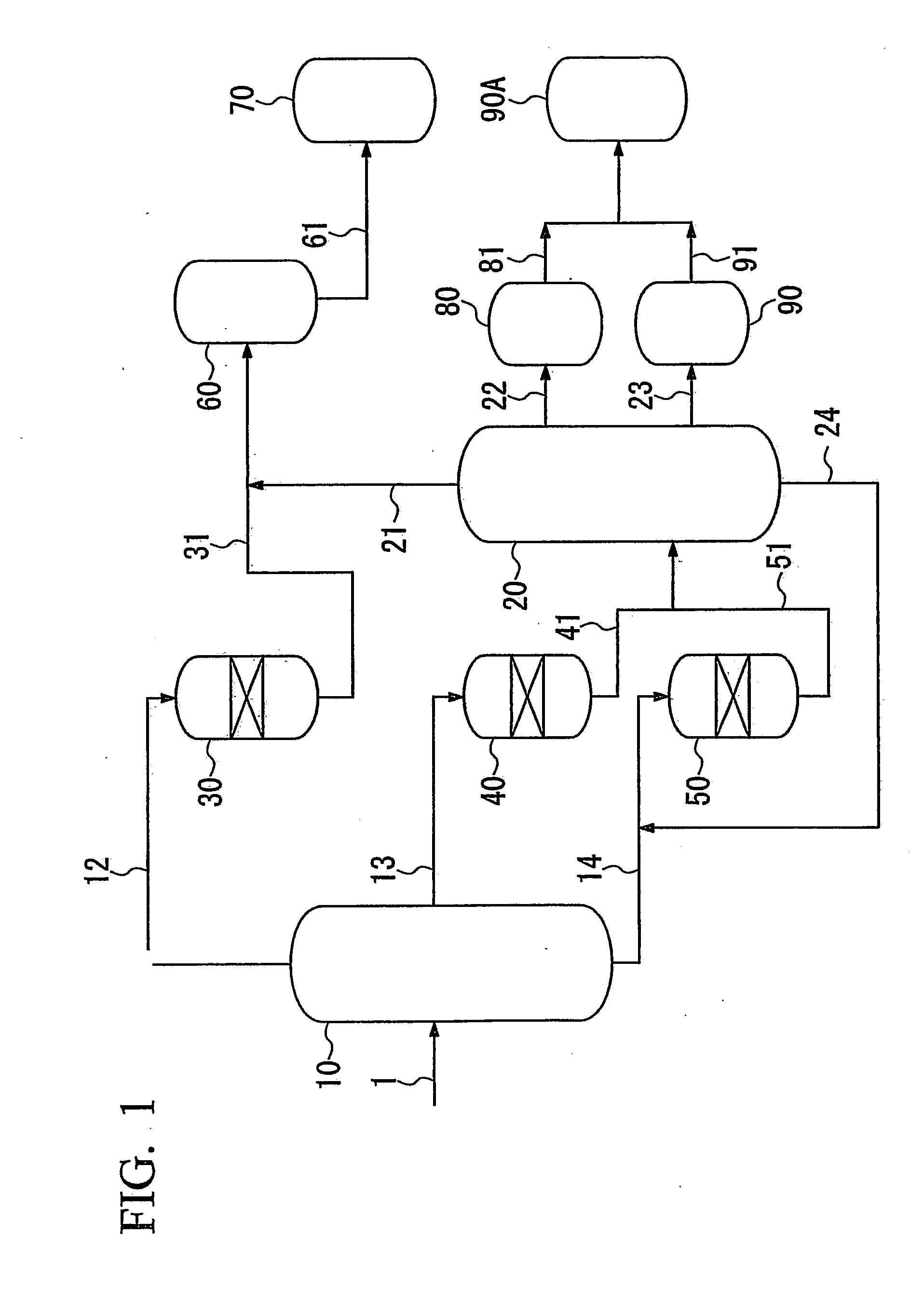
[0111]In the first fractionator, oil produced by a FT synthesis method (i.e. FT synthetic oil) (the content of hydrocarbons having a boiling point of 150° C. or higher was 84% by mass, and the content of hydrocarbons having a boiling point of 360° C. or higher was 42% by mass, based on the total amount of the FT synthetic oil (corresponding to the sum of hydrocarbons having 5 or more carbon atoms)) was fractionated into a naphtha fraction having a boiling point of less than 150° C., a first middle fraction having a boiling point of 150° C. to 350° C. and a wax fraction as a bottom fraction.

(Hydroisomerization of First Middle Fraction)

[0112]The hydroisomerizing reactor 40, which is a fixed-bed flow reactor, was filled with the catalyst A (150 ml), the above-obtained middle fraction was supplied thereto from the tower apex of the hydroisomerizing reactor 40 at a rate of 225 ml / h, and the middle fraction was hydrogen-treated ...

example 2

[0123]In this example, the fractionation of FT synthetic oil, the hydroisomerization of the first middle fraction, the hydrocracking of the wax fraction, and the fractionation of hydroisomerized products and hydrocracked products were performed in the same manner as in Example 1.

(Prediction of Kinematic Viscosity and Pour Point)

[0124]Assuming that 40% by mass of the kerosene fraction 1 was blended with 60% by mass of the gas oil fraction 1 to produce a diesel fuel, an average molecular weight (x[M.W.]) of the diesel fuel and the content (nC19+) of n-paraffins having 19 or more carbon atoms in the diesel fuel were predicted based on the all component analysis. The predicted values are shown in Table 3. The kinematic viscosity at 30° C. and the PP of the diesel fuel are calculated by applying x[M.W.] and [nC19+] to the above-mentioned Equations 1 and 2 and the calculated values are also shown in Table 3.

[0125]The kinematic viscosity at 30° C. (calculated value) and PP (calculated valu...

example 3

Fractionation of FT Synthetic Oil

[0126]In the first fractionator, oil produced by a FT synthesis method (i.e. FT synthetic oil) (the content of hydrocarbons having a boiling point of 150° C. or higher was 84% by mass, and the content of hydrocarbons having a boiling point of 360° C. or higher was 42% by mass, based on the total amount of the FT synthetic oil (corresponding to the sum of hydrocarbons having 5 or more carbon atoms)) was fractionated into a naphtha fraction having a boiling point of less than 150° C., a first middle fraction having a boiling point of 150° C. to 350° C. and a wax fraction as a bottom fraction.

(Hydroisomerization of First Middle Fraction)

[0127]The fixed-bed flow reactor was filled with the catalyst A (150 ml), the above-obtained middle fraction was supplied thereto from the tower apex of the hydroisomerizing reactor 40 at a rate of 225 ml / h, and the middle fraction was hydrogen-treated in a hydrogen stream under reaction conditions shown in Table 1.

[0128...


PUM

PropertyMeasurementUnit
pour pointaaaaaaaaaa
kinematic viscosityaaaaaaaaaa
pour pointaaaaaaaaaa

Abstract

Provided is A method of manufacturing diesel fuel, including: fractionating in a first fractionator a synthetic oil obtained by Fisher-Tropsch synthesis into at least two fractions of a middle fraction, and a wax fraction containing a wax component heavier than the middle fraction; hydroisomerizing the middle fraction by bringing the middle fraction into contact with a hydroisomerizing catalyst to produce a hydroisomerized middle fraction; hydrocracking the wax fraction by bringing the wax fraction into contact with a hydrocracking catalyst to produce a wax decomposition compound; fractionating in a second fractionator a mixture of the hydroisomerized middle fraction and the hydrocracked wax fraction into at least two fractions including a kerosene fraction and a gas oil fraction; and mixing the at least two fractions at a predetermined blend ratio to produce a diesel fuel having a kinematic viscosity at 30° C. of 2.5 mm2/s or more and a pour point of −7.5° C. or less.

Description

TECHNICAL FIELD[0001]The present invention relates to a method of manufacturing diesel fuel from synthetic oil obtained according to a Fisher-Tropsch synthesis method.BACKGROUND ART[0002]In recent years, from the standpoint of reduction of environmental burdens, there has been a need for a clean liquid fuel which has a low content of sulfur and aromatic hydrocarbons and is compatible with the environment. Thus, in the petroleum industry, a Fisher-Tropsch synthesis method (hereinafter abbreviated as “FT synthesis method) using carbon monoxide and hydrogen as raw materials has been investigated as a method of manufacturing a clean fuel. The FT synthesis method has high expectations since it can manufacture a liquid fuel base stock which has an abundance of paraffin and which does not contain sulfur, for example, a diesel fuel base stock. For example, Patent Document 1 discloses a fuel oil compatible with the environment.[0003]Patent Document 1: Japanese Unexamined Patent Application, ...

Claims


Application Information

Patent Timeline
Patent Type & Authority Applications(United States)
IPC IPC(8): C10G63/02
CPCC10G45/58C10G47/00C10G65/14C10G2400/04C10G2300/4018C10G2300/1022C10G2300/302C10G2300/304C10L1/08
Inventor TANAKA, YUICHI
Owner JAPAN OIL GAS & METALS NAT CORP
Why Eureka
Try Eureka