

Jaw insert for gripping a cylindrical member and method of manufacture
a cylindrical member and jaw insert technology, applied in the direction of chucks, manufacturing tools, mechanical equipment, etc., can solve the problems of difficult breakout, irreversible damage of pipes, and inability to achieve stress and corrosion concentrations in tubulars, etc., to achieve the effect of convenient manufacturing and convenient manufacturing
- Summary
- Abstract
- Description
- Claims
- Application Information
AI Technical Summary
Benefits of technology
Problems solved by technology
Method used
Image

Examples
Embodiment Construction
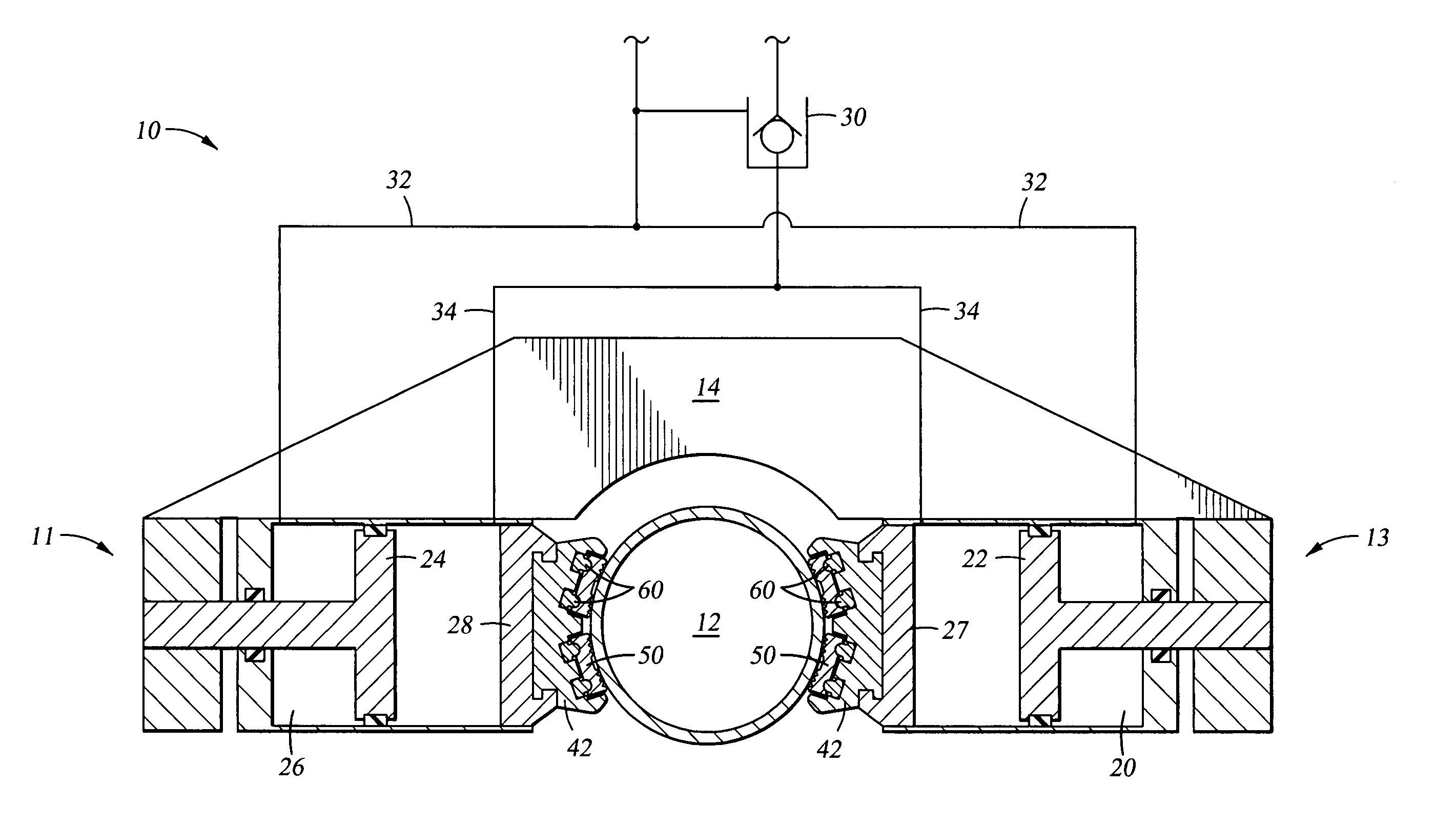
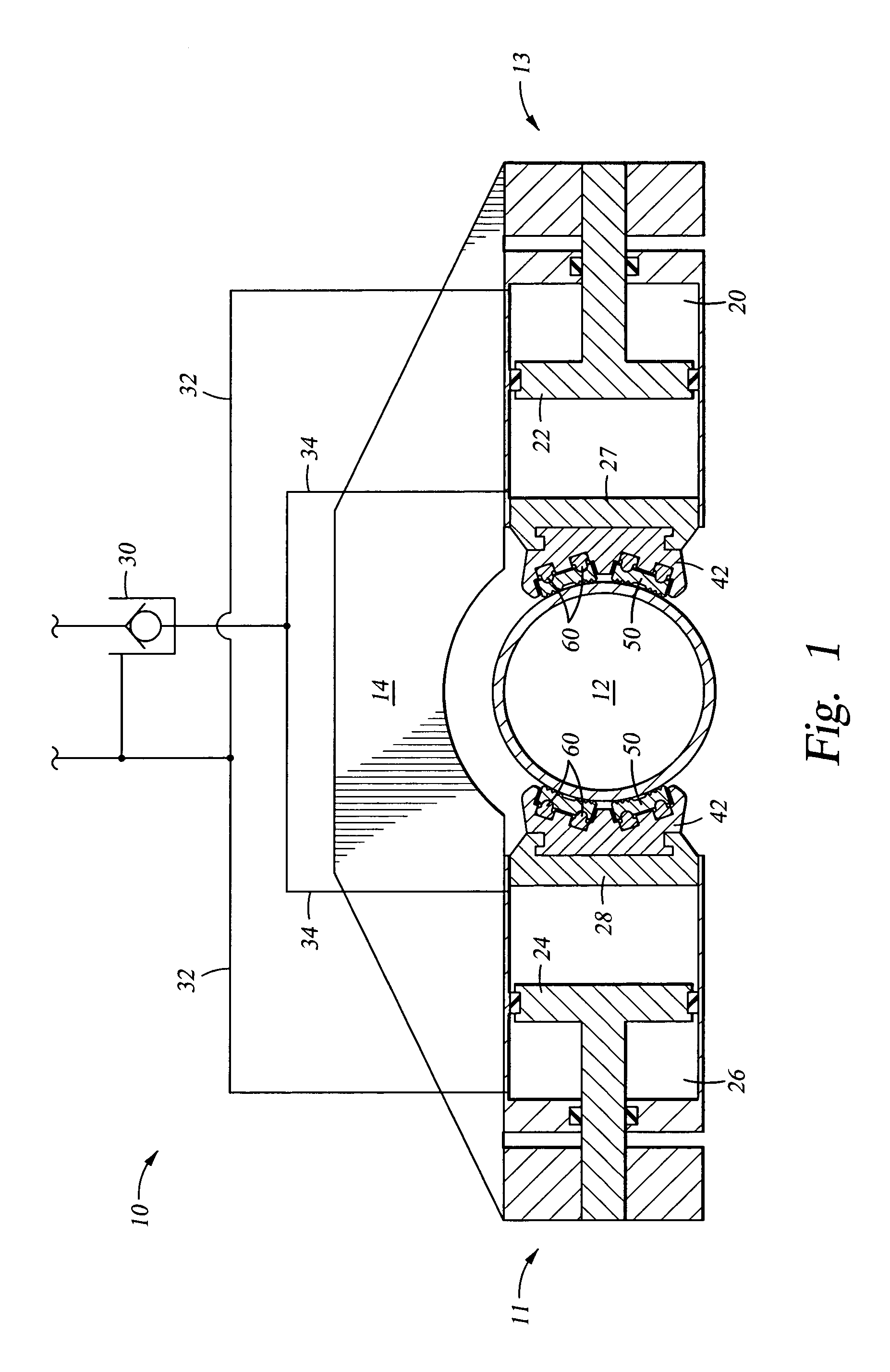
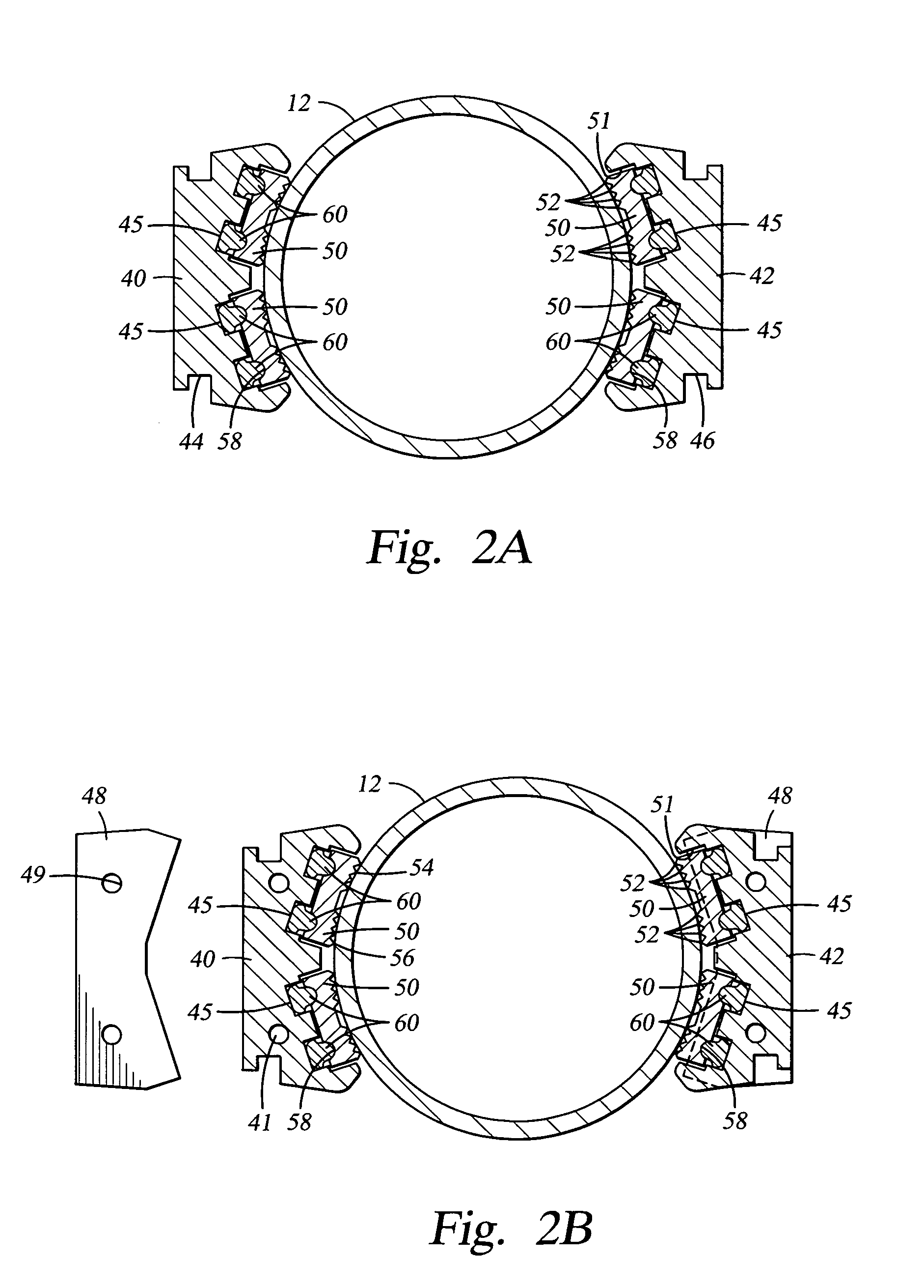
[0013]The embodiments described herein provide a gripping insert for use in a power tong or wrench for gripping a cylindrical member having at least two substantially adjacent rows of gripping teeth, where at least one row of teeth is offset or staggered longitudinally from an immediately adjacent row of teeth. The embodiments described herein provide a resistance or penetration profile that is substantially continuous and does not oscillate over a length of the gripping insert approaching 100% of the length of the entire insert.
[0014]In one embodiment, the gripping insert has at least two substantially adjacent rows of gripping teeth, where at least one row of teeth is offset or staggered longitudinally from an immediately adjacent row of teeth, and where the teeth in each substantially adjacent row are canted or angled in the same direction. In the present embodiment, the insert also provides a resistance or penetration profile that is substantially continuous and does not oscilla...
PUM
 Abstract
Description
Claims
Application Information