Protective assembly

a technology of protection assembly and shielding plate, which is applied in the direction of magnetic bodies, ultrathin/granular films, therapy, etc., can solve the problems of difficult control of current delivered through shock, heart tissue near the point of contact with the electrode can be severely damaged, and the approach is not effective in limiting current flow, etc., to achieve the effect of limiting the current flow

Inactive Publication Date: 2005-12-06
BIOPHAN TECH
View PDF7 Cites 245 Cited by
  • Summary
  • Abstract
  • Description
  • Claims
  • Application Information

AI Technical Summary

Problems solved by technology

At columns 1 and 2 of this patent, it is disclosed that: “Until now, however, there has been a reluctance to place patients with pacemakers in an MRI apparatus . . . . The RF field produced in the MRI system represents a form of electromagnetic interference (EMI) that is very harzardous to the pacemaker.
. . this approach is not effective to limit the current flow between the heart tissue and the electrode at the distal end of the pacemaker lead.
As a result, the heart tissue near the point of contact with the electrode can be severely damaged when high-voltage defibrillation pulses are applied to the heart.” U.S. Pat. No. 4,320,763 also discloses that such tissue damage can be prevented by connecting a current limiting device such as a diode or a pair of field effect transistors (FETs) in series between a pacemaker output terminal and a distal electrode.
. . because the impedance of the heart tissues through which the shocks are discharged are unknown, it is difficult to control the current delivered through the shocks.
Abnormally high current levels are undesirable because a high current may damage the heart tissues.”
In spite of their disclosures, and the disclosures of many comparable United States and foreign patents, it does not appear that anyone has yet come up with a satisfactory solution to the problem of heat-induced tissue damage that occurs during MRI imaging processes.
. . it is not possible to design a device for use in an MR environment incorporating long metallic parts such as guide wires, mechanical cables, or electrical leads, and be completely sure of safety.

Method used


Image

  • Protective assembly
  • Protective assembly
  • Protective assembly

Examples


Embodiment Construction

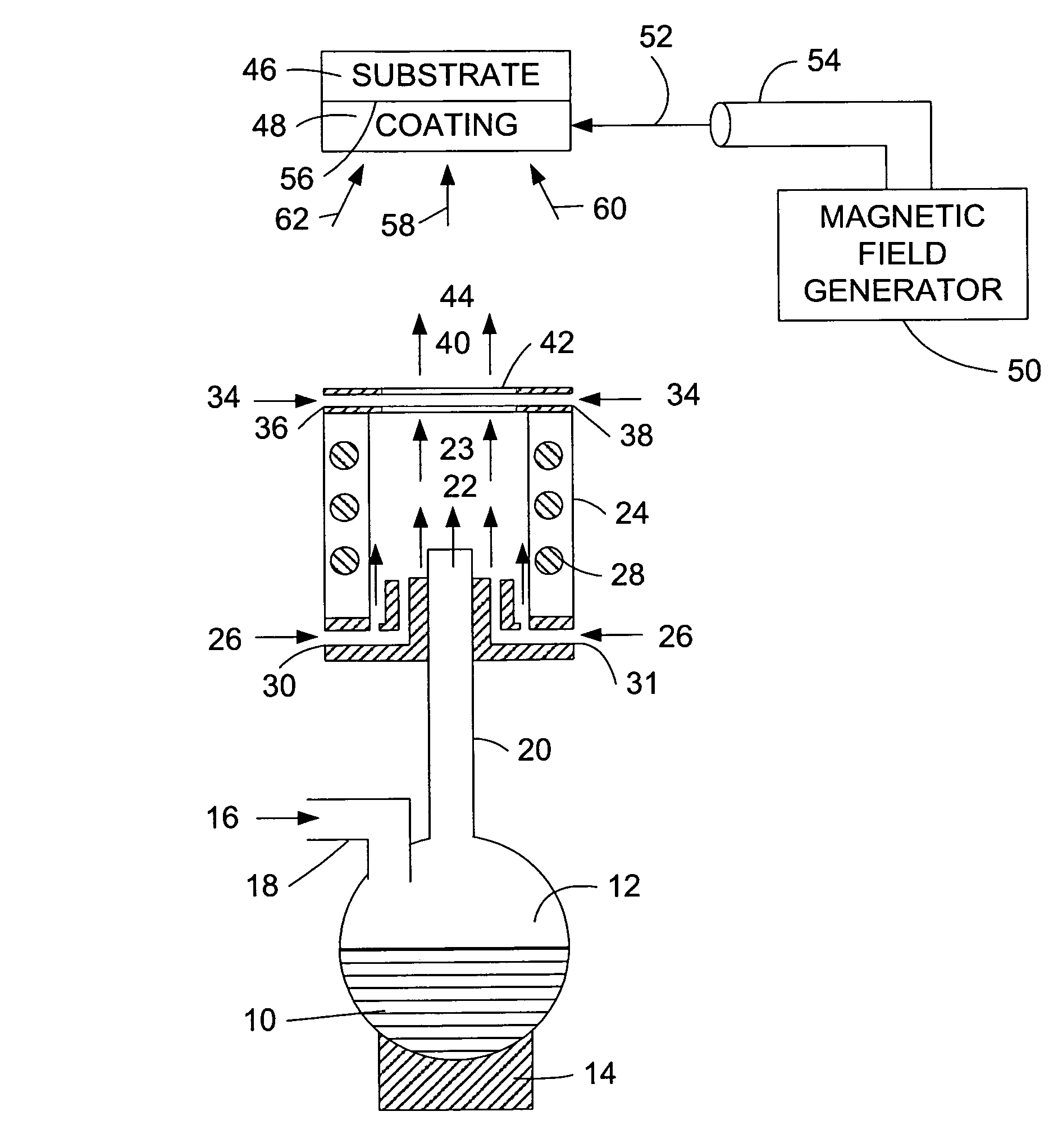
[0040]FIG. 1 is a schematic illustration of one process of the invention which may be used to make nanomagnetic material. This FIG. 1 is similar in many respects to the FIG. 1 of U.S. Pat. No. 5,213,851, the entire disclosure of which is hereby incorporated by reference into this specification.

[0041]Referring to FIG. 1, and in the preferred embodiment depicted therein, it is preferred that the reagents charged into misting chamber 12 will be sufficient to form a nano-sized ferrite in the process. The term ferrite, as used in this specification, refers to a material that exhibits ferromagnetism. Ferromagnetism is a property, exhibited by certain metals, alloys, and compounds of the transition (iron group) rare earth and actinide elements, in which the internal magnetic moments spontaneously organize in a common direction; ferromagnetism gives rise to a permeability considerably greater than that of vacuum and to magnetic hysteresis. See, e.g, page 706 of Sybil B. Parker's “McGraw-Hil...


PUM

PropertyMeasurementUnit
temperatureaaaaaaaaaa
frequencyaaaaaaaaaa
frequencyaaaaaaaaaa

Abstract

An assembly for protecting biological tissue from the effects of heating. The assembly contains a conductor in contact with the biological tissue and forming an electrical circuit comprising the biological tissue. The assembly contains a device for modifying the impedance of the electrical circuit such that, at a frequency of from about 10 megahertz to about 150 megahertz, such impedance is at least about 0.5 ohms per centimeter of length of said conductor. The assembly also contains a device for limiting the flow of current through the biological tissue such that, when the assembly is exposed to an alternating current electromagnetic field at a frequency of 64 megahertz and a magnetic field strength of 1.5 Tesla for 15 minutes, the temperature of the biological tissue does not exceed 42 degrees Celsius.

Description

CROSS-REFERENCE TO RELATED PATENT APPLICATION[0001]This patent application is a continuation-in-part of applicants' patent application U.S. Ser. No. 10 / 324,773, filed on Dec. 18, 2002 now U.S. Pat. No. 6,864,418.FIELD OF THE INVENTION[0002]An assembly for protecting biological tissue from the effects of heating comprising a conductor in contact with such biological tissue and forming an electrical circuit comprising such biological tissue, wherein such assembly is comprised of means for modifying the impedance of the electrical circuit such that, at a frequency of from about 10 megahertz to about 150 megahertz, such impedance is at least about 0.5 ohms per centimeter of length of said conductor, and wherein said assembly is comprised of means for limiting the flow of current through said biological tissue such that, when said assembly is exposed to an alternating electromagnetic field at a frequency of 64 megahertz and a direct current magnetic field strength of 1.5 Tesla for 15 min...

Claims


Application Information

Patent Timeline
Patent Type & Authority Patents(United States)
IPC IPC(8): A61N1/16H01B7/04H01B11/10H01F10/00H01F10/32
CPCA61N1/16B82Y25/00H01B11/10H01F10/007H01F1/0063H01F10/324Y10T428/2982Y10T428/25Y10T428/27Y10T428/24992
Inventor WANG, XINGWUGREENWALD, HOWARD J.HELFER, JEFFREY L.GRAY, ROBERT W.
Owner BIOPHAN TECH
Why Eureka
Try Eureka