
Apparatus for repairing an underwater pipe

a technology for underwater pipes and accessories, applied in the direction of pipe laying and repair, application, pipe elements, etc., can solve the problems of further cost incurred through pipeline shut down, pipe damage, and inability to withstand such loads, and achieves quick and simple installation, small overall clamp dimension, and strong repair

Inactive Publication Date: 2005-12-06
TAYLOR KERR COUPLINGS
View PDF31 Cites 33 Cited by
  • Summary
  • Abstract
  • Description
  • Claims
  • Application Information

AI Technical Summary

Benefits of technology

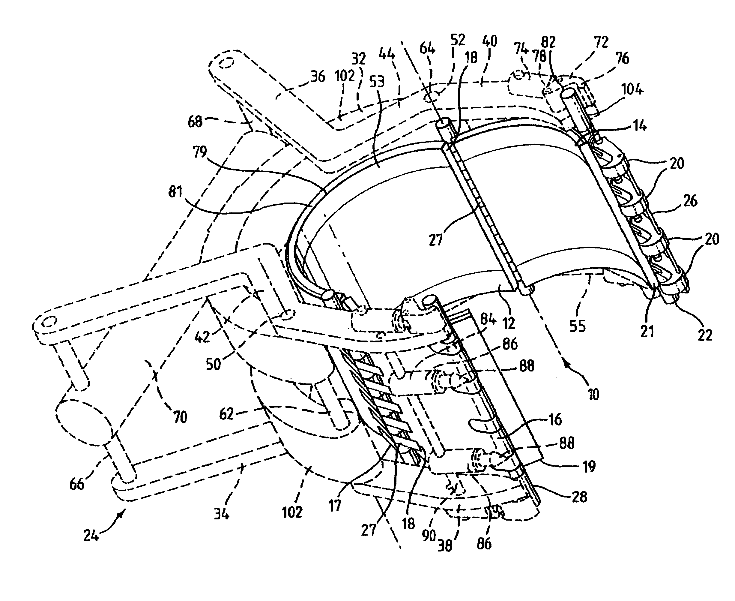
[0008]It is an object of the present invention to provide a clamp which is quick and simple to install. The part-cylindrical portions when hinged apart provide a large gap that enables the clamp to be installed around a pipe whilst working within a confined space. The hinging of the part-cylindrical sections to one another means that the sections are at all times aligned relative to one another and do not have to be brought into register in the difficult conditions underwater. The fastening means hold the free edges together to provide a strong repair.
[0012]Fastening the part-cylindrical portions together using the latch and latch-engaging surface enables a clamp to be constructed which can be quickly fastened deep underwater using a simple tool.
[0014]In a preferred embodiment, the at least one latch is biased to engage with the at least one latch-engaging surface. Using such a biasing arrangement means that moving the edges of the longitudinal gap together or the free longitudinal edges of the part-cylindrical portions together can provide sufficient force to engage the or each latch with at least one of the at least one latch-engaging surfaces to hold the edges of the longitudinal gap together or the free longitudinal edges of the part-cylindrical portions together.
[0016]The means for engaging with a latch release tool provides the advantage that the or each latch can be easily removed if the clamp is positioned incorrectly on the pipe or if it needs to be removed for any other reason.
[0018]Such a coupling has the advantage that, the latches can be moved to engage the latch-engaging surfaces all at the same time. This can make it easier to secure the clamp. Secondly, disengagement of the clamp is simplified because all the latches can be released from the latch-engaging surfaces at the same time.

Problems solved by technology

Pipes, and in particular flexible pipes, are highly susceptible to corrosion which damages the pipes and can cause leaks.
If the pipe is damaged, its ability to withstand such loads is significantly reduced.
Further cost will be incurred through the pipeline being shut down while the repair is carried out.
Repairing a pipe in-situ deep underwater is extremely difficult and pipe manufacturers usually advise their customers to take out the damaged pipe section completely and bring it out of the water for repair.
Difficulties are caused by the extreme depths at which the pipes are located.
At these depths, diver intervention is not usually possible and the pipes can only be accessed using remotely operable vehicles (ROVs).
The problem of repairing deep sea pipes is further increased for dynamic risers.
If a dynamic section is damaged, repair tools must move with the dynamic section or, alternatively, the repair must be carried out extremely rapidly.
However, using these bolt clamps is problematical for a number of reasons.
Firstly, the installation process is extremely complex and so specialist ROVs and ROV crews are required.
Secondly, these types of clamp are very heavy and they change the dynamics of the dynamic risers.
Thirdly, pipes and in particular dynamic risers are usually tethered and these tethers provide an obstruction to both the tools for attaching the clamp and the clamp itself.
There are many problems with this method.
Firstly, because the adhesive is prepared at the surface it must be quickly applied to the damaged pipe before the adhesive sets.
Secondly, this type of repair is very weak and with a patch installed the maximum operating pressure of the pipe is significantly reduced.
Thirdly, although the tooling required to install a patch to a stationary pipe is quite simple, albeit heavy, the ROV tooling required to install a patch using adhesive to a dynamic riser is complex and requires a specialist ROV crew.

Method used


Image

  • Apparatus for repairing an underwater pipe
  • Apparatus for repairing an underwater pipe
  • Apparatus for repairing an underwater pipe

Examples


Embodiment Construction

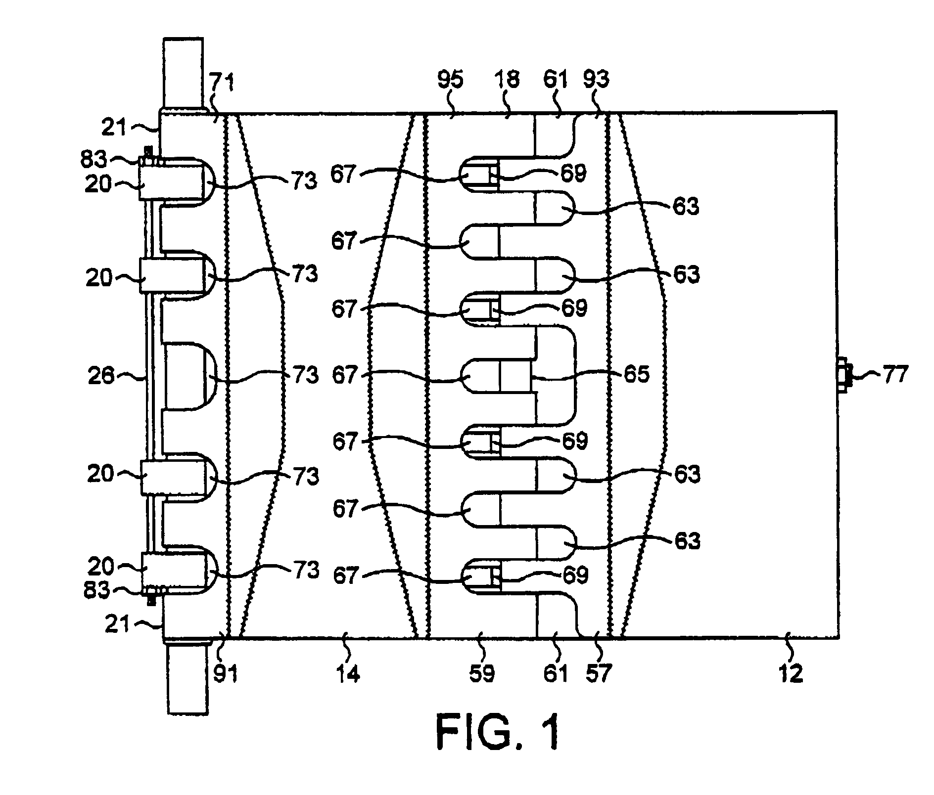
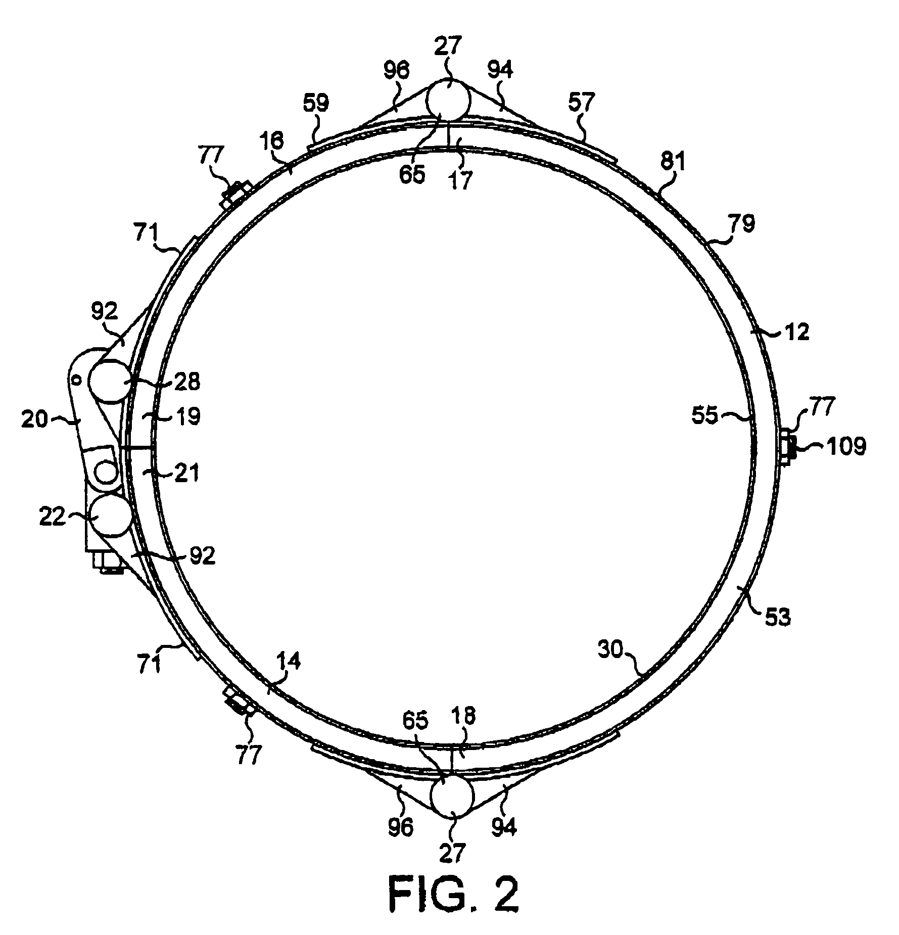
[0033]Referring to FIGS. 1 to 3, a pipe clamp 10 is shown comprising three part-cylindrical portions 12,14,16 hinged together along adjacent longitudinal edges 17,18. A first of the part-cylindrical portions 12 is hinged to a respective one of the other two part-cylindrical portions 14,16 along each of its longitudinal edges 17,18 by hinges 27. Each of the other part-cylindrical portions 14,16 is hinged to the first part-cylindrical portion 12 on one longitudinal edge 17,18, its other longitudinal edge 19,21 is free. The first part-cylindrical portion 12 subtends one half of the circumference of the pipe clamp 10. The other two part-cylindrical portions 14,16 each subtend one quarter of the circumference of the, pipe clamp 10, when the pipe clamp 10 is in a closed position (as shown in FIGS. 1 to 3).

[0034]The part-cylindrical portions 14,16 are movable about the hinge axes 27 towards and away from one another between an open position in which the free longitudinal edges 19,21 are sp...


PUM


Abstract

A pipe clamp 10 for repairing an underwater pipe. The pipe clamp 10 comprises a plurality of part-cylindrical portions 12,14,16 hinged together along a hinge axis or axes 27 along adjacent longitudinal edges 17,18. Two or the longitudinal edges 20,21 of the part-cylindrical portions are free. The part-cylindrical portions 12,14,16 are movable about the hinge axis or axes 27 towards and away from one another between an open position in which the free longitudinal edges 20,21 are spaced apart and the clamp 10 can be placed around a pipe and a closed position in which, in use, the free longitudinal edges 20,21 of the part-cylindrical portions 12,14,16 are brought together around the pipe. Fastening means are provided for holding the free edges 20,21 of the part-cylindrical portions 12,14,16 together, such that, in use, the clamp 10 is held to the pipe.

Description

[0001]The present invention relates to a pipe clamp for repairing an underwater pipe, and a method of repairing an underwater pipe.BACKGROUND OF THE INVENTION[0002]Pipes located deep under the sea are used extensively for the transportation of oil, natural gas and other fluids. Pipes, and in particular flexible pipes, are highly susceptible to corrosion which damages the pipes and can cause leaks. Flexible pipes used as dynamic risers are designed to withstand a dynamic load. If the pipe is damaged, its ability to withstand such loads is significantly reduced.[0003]When a pipe becomes damaged, the pipe can either be replaced or repaired. In 2002 the typical coat of replacement of a single flexible pipe used as a dynamic riser is £5 million. Further cost will be incurred through the pipeline being shut down while the repair is carried out. Repairing a pipe in-situ deep underwater is extremely difficult and pipe manufacturers usually advise their customers to take out the damaged pipe...

Claims


Application Information

Patent Timeline
Patent Type & Authority Patents(United States)
IPC IPC(8): F16L1/26F16L55/17F16L55/18
CPCF16L1/26F16L55/18F16L55/1715Y10T24/1418F16L55/17
Inventor TAYLOR, NEIL JOHN THORNTONWEBB, IAN RICHARD
Owner TAYLOR KERR COUPLINGS
Learn More