Connection structure for a striking plate of a golf club head

a golf club head and connection structure technology, applied in the field of golf club head connection structure, can solve the problems of inability to meet the needs of golf clubs, and long time required to proceed with vacuuming or handling inert gas, and achieve the effect of increasing the bonding area between the two and the bonding strength

Inactive Publication Date: 2005-12-06
FUSHENG PRECISION
View PDF8 Cites 54 Cited by
  • Summary
  • Abstract
  • Description
  • Claims
  • Application Information

AI Technical Summary

Benefits of technology

[0006]An object of the present invention is to provide a golf club head including a club head body and a striking plate bonded to the club head body, wherein the bonding strength between the club head body and the striking plate is increased by means of increasing the bonding area therebetween.
[0008]To achieve the aforementioned objects, the present invention provides a golf club head including a club head body, a striking plate, and a bonding layer. The club head body includes an engaging portion on a front side thereof. The striking plate includes an engaging portion on a rear side thereof. The engaging portion of the striking plate is engaged with the engaging portion of the club head body. One of the engaging portion of the striking plate and the engaging portion of the club head body includes at least one groove, and the other of the engaging portion of the striking plate and the engaging portion of the club head body includes at least one protrusion. The bonding layer is applied between the engaging portion of the club head body and the engaging portion of the striking plate. The groove and the protrusion of the engaging portion of the club head body and the engaging portion of the striking plate increase a contact area between the club head body and the striking plate, thereby improving a bonding strength between the club head body and the striking plate.
[0009]In another embodiment of the invention, the groove and the protrusion are replaced with an inner flange and an outer flange which are preferably zigzag to further increase the bonding effect between the club head body and the striking plate.

Problems solved by technology

Nevertheless, these methods have their respective disadvantages.
Problems would arise if the material for the club head body is different from that for the striking plate when using welding.
And it takes a long time to proceed with vacuuming or handling of inert gas for preventing oxidation of the metal surfaces when high energy welding such as laser welding or plasma welding is adopted.
Nevertheless, since the bonding strength of the high strength bonding agent has its limitation and since the striking plate 20 is subject to a shear force up to 4100 psi when striking a golf ball, the is no guarantee to maintain the bonding between the club head body 10 and the striking plate 20 although the bonding process saves time for manufacture.

Method used


Image

  • Connection structure for a striking plate of a golf club head
  • Connection structure for a striking plate of a golf club head
  • Connection structure for a striking plate of a golf club head

Examples


Embodiment Construction

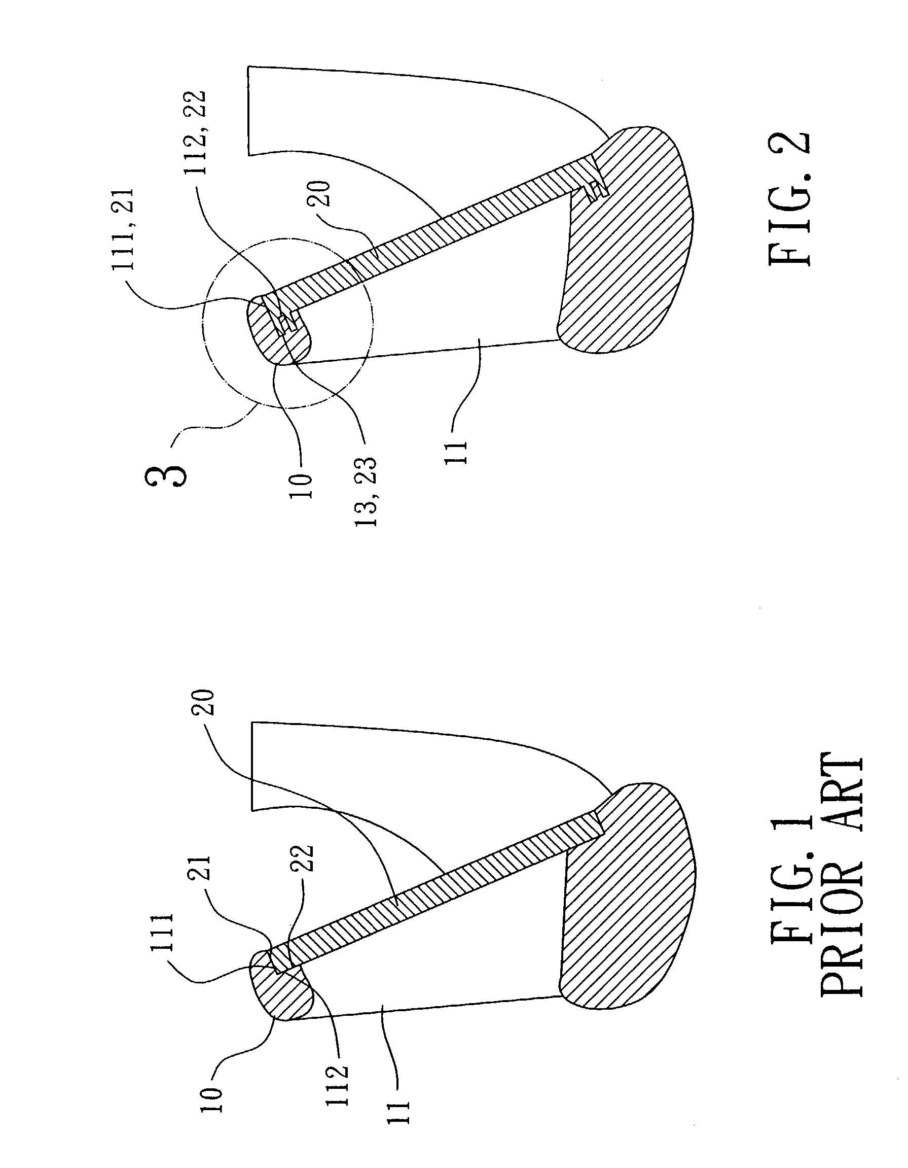
[0022]The present invention is now to be described hereinafter in detail, in which the same reference numerals are used for the same parts as those in the prior art.

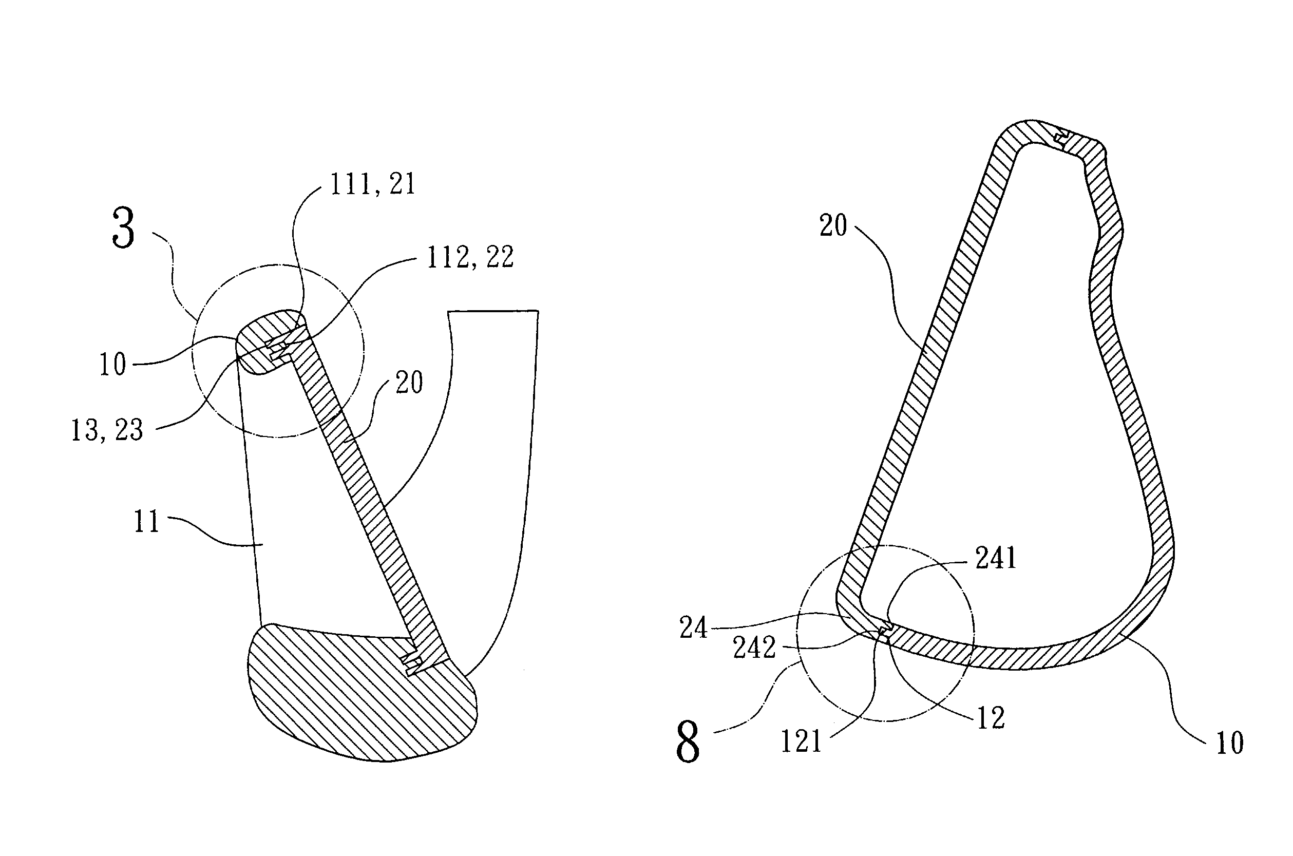
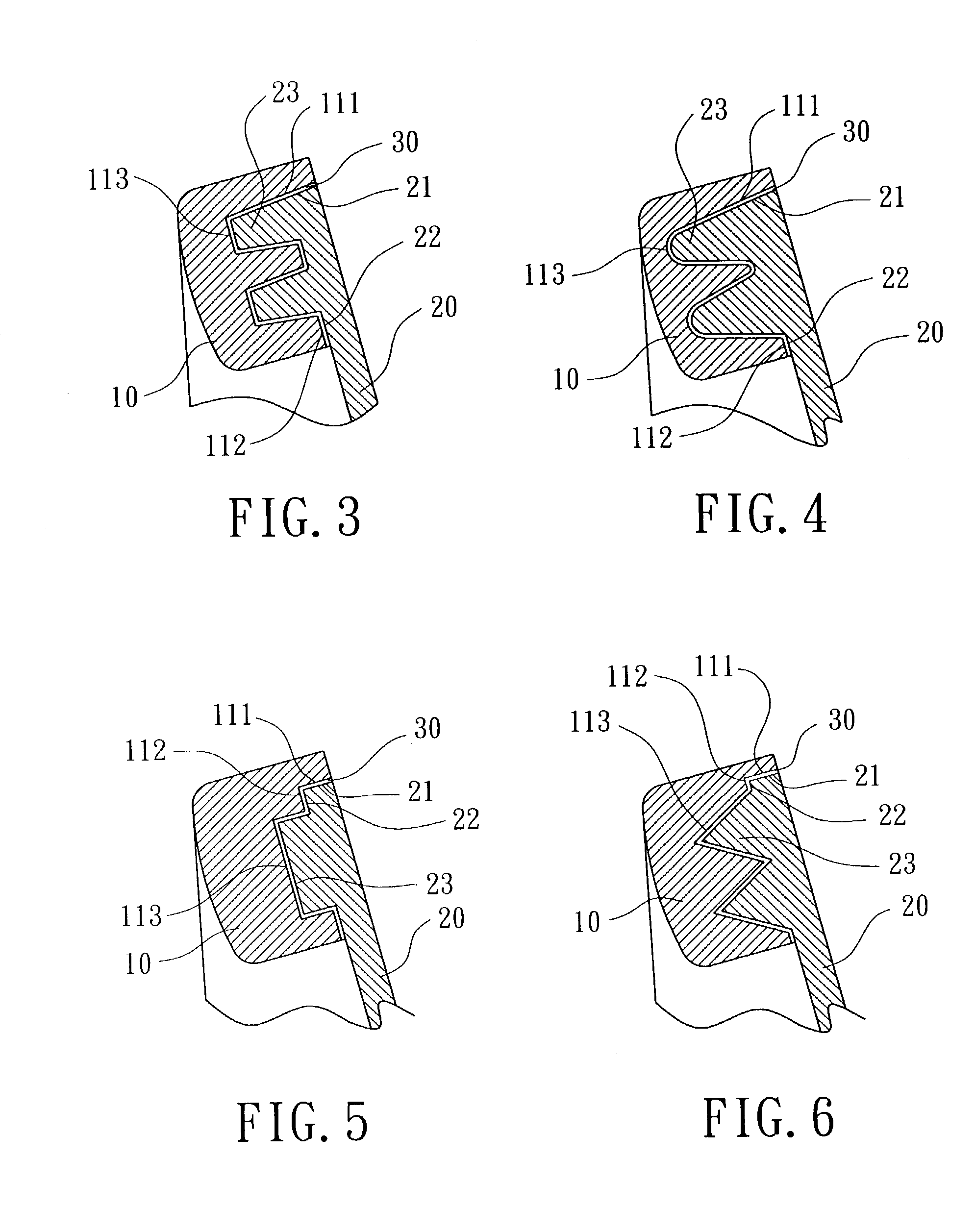
[0023]Referring to FIGS. 2 and 3, a golf club head in accordance with the present invention includes a club head body 10, a striking plate 20, and a bonding layer 30. The club head body 10 may be a club head body for an iron club, a wooden club, or a putter. The club head body 10 includes a recessed portion 11 for receiving the striking plate 20. The recessed portion 11 includes an inner periphery 111 and an engaging portion 112 that has at least one groove 113.

[0024]The striking plate 20 is a metal plate formed by means of casting, forging, or machining. The striking plate 20 includes an outer periphery 21 for engaging with the inner periphery 111 of the recessed portion 11 of the club head body 10. The striking plate 20 further has an engaging portion 22 on a lip on a rear side thereof. The engaging portion 22 of the s...


PUM


Abstract

A golf club head includes a club head body, a striking plate, and a bonding layer. The striking plate includes an engaging portion that is engaged with an engaging portion of the striking plate. One of the engaging portion of the striking plate and the engaging portion of the club head body includes at least one groove, and the other includes at least one protrusion. The bonding layer is applied between the engaging portion of the club head body and the engaging portion of the striking plate. The groove and the protrusion of the engaging portion of the club head body and the engaging portion of the striking plate increase a contact area between the club head body and the striking plate, thereby improving a bonding strength between the club head body and the striking plate.

Description

BACKGROUND OF THE INVENTION[0001]1. Field of the Invention[0002]The present invention relates to a connection structure for a striking plate of a golf club head.[0003]2. Description of Related Art[0004]A typical golf club head includes a striking plate that is engaged with the club head body by insertion, argon welding, hard soldering or high energy welding. Nevertheless, these methods have their respective disadvantages. More specifically, the striking plate is apt to be deformed when engaged with the club head body by insertion. Problems would arise if the material for the club head body is different from that for the striking plate when using welding. And it takes a long time to proceed with vacuuming or handling of inert gas for preventing oxidation of the metal surfaces when high energy welding such as laser welding or plasma welding is adopted.[0005]To overcome the above disadvantages, a bonding technique using high strength resin at room temperature has been proposed. FIG. 1 ...

Claims


Application Information

Patent Timeline
Patent Type & Authority Patents(United States)
IPC IPC(8): A63B53/04
CPCA63B53/04A63B53/047A63B2053/0416A63B53/0416A63B60/00
Inventor CHEN, CHAN-TUNG
Owner FUSHENG PRECISION
Why Eureka
Try Eureka