Pulse frequency modulated voltage regulator capable of prolonging a minimum off-time

a voltage regulator and pulse frequency technology, applied in the field of pulse frequency modulated voltage regulators, can solve the problems of reducing the efficiency of pwm voltage regulators, pfm voltage regulators in heavy loading conditions suffer from a great ripple of output voltage, and pwm voltage regulators have a drawback of becoming low efficiency regulators, so as to prolong the minimum off-time and reduce the ripple of output voltages.

Active Publication Date: 2005-12-06
GLOBAL MIXED MODE TECH
View PDF7 Cites 64 Cited by
  • Summary
  • Abstract
  • Description
  • Claims
  • Application Information

AI Technical Summary

Benefits of technology

[0013]In view of the above-mentioned problems, an object of the present invention is to provide a PFM voltage regulator capable of prolonging a minimum OFF-time, thereby reducing a ripple of an output voltage in a heavy loading condition.
[0014]Another object of the present invention is to provide a PFM voltage regulator capable of prolonging a minimum OFF-time, thereby becoming operable not only in a light loading condition but also in a heavy loading condition.
[0015]Still another object of the present invention is to provide a PFM voltage regulator capable of prolonging a minimum OFF-time, thereby shortening a transient period from start-up to a stable operational state.
[0020]According to another aspect of the present invention, the PFM voltage regulator includes an inductive means and a capacitive means. The inductive means is coupled to a DC voltage source. The capacitive means has a terminal which is coupled to the inductive means and provides an output voltage. A PFM switching controller generates a PFM switching signal for converting the DC voltage source to the output voltage. In response to the output voltage, a feedback circuit generates a feedback signal. A minimum time controller is coupled to the PFM switching controller for controlling a minimum time of each period of the PFM switching signal spent on delivering energy from the inductive means to the capacitive means. When the output voltage is lower than a predetermined target voltage, a time prolonging circuit prolongs the minimum timespent on delivering energy from the inductive means to the capacitive means in response to the feedback signal.
[0021]Preferably, the minimum time spent on delivering energy from the inductive means to the capacitive means is prolonged along with an increase of the absolute difference between the output voltage and the predetermined target voltage.

Problems solved by technology

Neither the PFM voltage regulator nor the PWM voltage regulator can provide the same satisfactory performance when operated both in a light loading condition and in a heavy loading condition.
More specifically, the PFM voltage regulator in the heavy loading condition suffers from a great ripple of the output voltage.
On the other hand, the PWM voltage regulator has a drawback of becoming a low efficiency regulator in the light loading condition since the power consumption caused by the switching of the power switch transistor becomes relatively large with respect to the output power supplied.
However, the prior art voltage regulator is required to employ a complicated PWM and PFM dual mode switching circuit.
As clearly seen from FIG. 1(b), during the minimum OFF-time TOFF, min, the energy stored in the inductor L fails to be completely delivered to the capacitor C, which is contrary to the assumption of U.S. Pat. No. 5,801,518, since the inductor current IL does not decrease to zero, resulting in the impossibility of reaching the maximum possible peak value for the output voltage Vout.
As a result, the energy continuously stored in the inductor L is completely delivered at a time to the capacitor C, causing a very great output ripple.
Since the delivery of the energy between the inductor L and the capacitor C fails to achieve a good efficiency as described above, the conventional PFM voltage regulator 10 inevitably spends an disadvantageously longer time on a transient period from start-up to a stable operational state where the output voltage Vout reaches the target voltage Vo.

Method used


Image

  • Pulse frequency modulated voltage regulator capable of prolonging a minimum off-time
  • Pulse frequency modulated voltage regulator capable of prolonging a minimum off-time
  • Pulse frequency modulated voltage regulator capable of prolonging a minimum off-time

Examples


Embodiment Construction

[0032]The preferred embodiments according to the present invention will be described in detail with reference to the drawings.

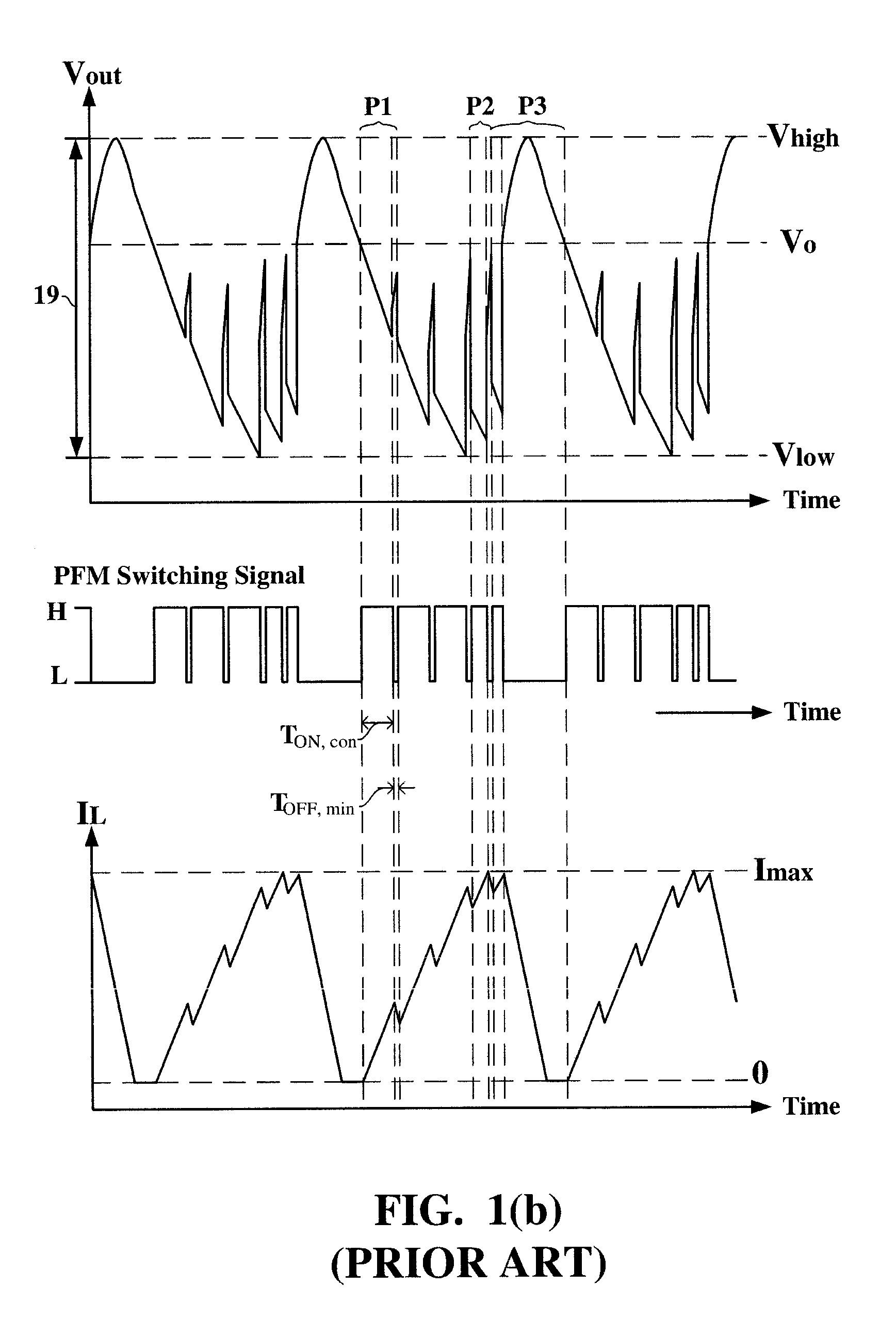
[0033]For clearer appreciation of features of the present invention, described first is how U.S. Pat. No. 5,801,518 adversely causes an even greater output ripple. Because the output voltage Vout in the heavy loading condition makes a change with a relatively larger degree of decrease during the OFF state of the power switch transistor Q (referred to as an OFF-time hereinafter), the prior art suggests that a shorter OFF-time be used to prevent the output voltage Vout from decreasing too much and a longer conductive time of the power switch transistor Q (referred to as an ON-time hereinafter) be used to store more energy in the inductor L for supplementing the capacitor C later. However, as shown in FIG. 1(b), once the output voltage Vout is lower than the target voltage Vo, the longer ON-time adversely causes the output voltage Vout to decrease more deeply an...


PUM


Abstract

In a pulse frequency modulated (PFM) voltage regulator, a PFM switching controller is provided to generate a PFM switching signal for converting a DC voltage source to an output voltage. A minimum OFF-time controller provides the PFM switching signal with a minimum OFF-time. In response to the output voltage, a feedback circuit generates a feedback signal. When the output voltage is lower than a predetermined target voltage, an OFF-time prolonging circuit prolongs the minimum OFF-time in response to the feedback signal. In other words, a time of delivering energy to a capacitor from an inductor may be prolonged by the OFF-time prolonging circuit. Therefore, a ripple of the output voltage is effectively reduced when the PFM voltage regulator is operated in a heavy loading condition.

Description

BACKGROUND OF INVENTION[0001]1. Field of the Invention[0002]The present invention relates to a pulse frequency modulated (PFM) voltage regulator and, more particularly, to a PFM voltage regulator capable of prolonging a minimum OFF-time, thereby reducing a ripple of an output voltage in a heavy loading condition.[0003]2. Description of the Related Art[0004]Typically, a voltage regulator is used for supplying an output voltage with a regulated voltage level from a DC voltage source by appropriately controlling a duty cycle of a power switch transistor. Depending on requirements of practical applications, the regulated output voltage may be higher or lower than the original DC voltage source. Of methods for controlling the duty cycle of the power switch transistor in the voltage regulator, the most frequently used are a PFM switching control mode and a pulse width modulated (PWM) switching control mode. The PFM voltage regulator turns on the power switch transistor each time when the ...

Claims


Application Information

Patent Timeline
Patent Type & Authority Patents(United States)
IPC IPC(8): H02M1/15
CPCH02M1/15H02M2001/0025H02M1/0025
Inventor TZENG, GUANG-NANCHEN, YUNG-CHIHLEE, RONG-CHIN
Owner GLOBAL MIXED MODE TECH
Why Eureka
Try Eureka