Calibrating a loop-filter of a phase locked loop

a technology of phase lock and loop filter, which is applied in the direction of filters, tunable filters, instruments, etc., can solve the problem of using a complicated calibration procedur

Inactive Publication Date: 2005-12-06
NOKIA TECH OY
View PDF7 Cites 20 Cited by
  • Summary
  • Abstract
  • Description
  • Claims
  • Application Information

AI Technical Summary

Benefits of technology

[0011]It is an advantage of the invention that the integrated loop-filter is calibrated automatically without a dedicated complicated calibration circuit. Measurements for RC-filter components of other entities integrated on the same chip are usually carried out anyway, and according to the invention, such measurement results are simply used as well for calibrating the loop-filter.
[0012]The RC-filter component of the other entity can be for instance the RC-filter component of a base-band filter of a transmitter chain or the RC-filter component of a channel-select filter of a receiver chain, but equally any other tunable RC-filter component, as long as it is integrated on the same chip as the loop-filter.
[0013]The tuning of an RC-filter of the loop-filter can be performed by changing the value of a resistor of the RC-filter component, the value of a capacitor of the RC-filter component, or both. For calibrating the loop-filter, the tuning according to the invention is preferably performed for all RC-filter components of the loop-filter.
[0014]The proposed unit can be any unit which requires on the one hand a PLL and on the other hand some entity with a tunable RC-filter component. Such a unit can be for example a communication unit, like a mobile terminal, comprising a transmitter chain and a receiver chain.
[0015]Other objects and features of the present invention will become apparent from the following detailed description considered in conjunction with the accompanying drawings. It is to be understood, however, that the drawings are designed solely for purposes of illustration and not as a definition of the limits of the invention, for which reference should be made to the appended claims. It should be further understood that the drawings are not drawn to scale and that they are merely intended to conceptually illustrate the structures and procedures described herein.BRIEF DESCRIPTION OF THE FIGURES
[0016]FIG. 1 schematically presents a block diagram of an embodiment of an IC chip according to the invention; and

Problems solved by technology

When an integrated loop-filter is used nevertheless, a complicated calibration procedure is employed.

Method used


Image

  • Calibrating a loop-filter of a phase locked loop
  • Calibrating a loop-filter of a phase locked loop
  • Calibrating a loop-filter of a phase locked loop

Examples


Embodiment Construction

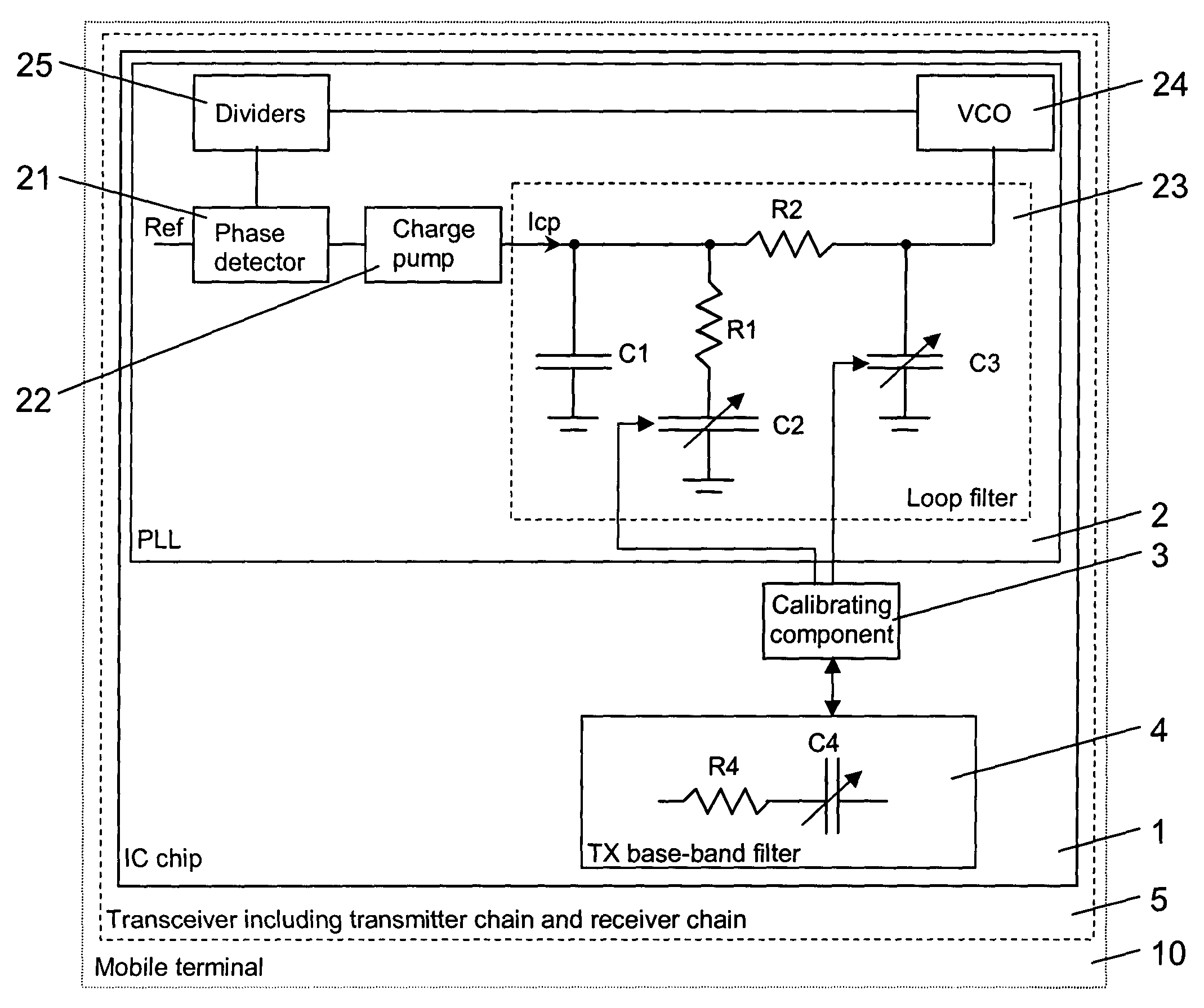
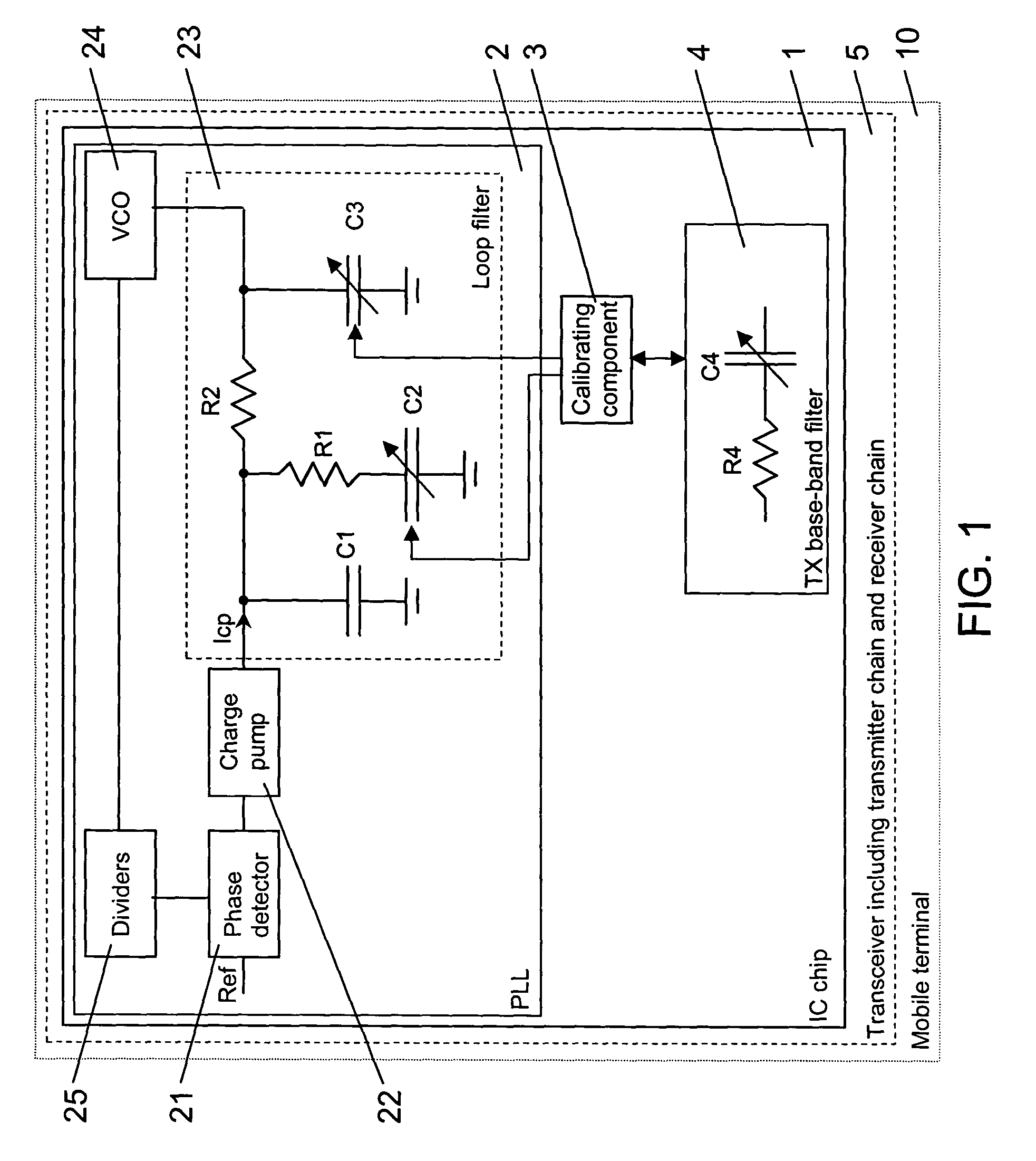
[0018]FIG. 1 schematically presents a preferred embodiment of an IC chip 1 according to the invention. The IC chip 1 is for use in a transceiver 5 of a mobile terminal 10, e.g. a cellular phone, which is indicated in FIG. 1 with dotted lines. The transceiver 5, which is indicated in FIG. 1 with dashed lines, includes a transmitter chain and a receiver chain.

[0019]The IC chip 1 comprises a PLL 2, a calibrating component 3 and at least a base-band filter 4 of the transmitter chain of the transceiver 5.

[0020]The PLL 2 includes, connected to each other in a loop in this order, a phase detector 21, a charge pump 22, a loop-filter 23, a VCO 24 and programmable frequency dividers 25.

[0021]The output of the charge pump 22 is thus connected to the input of the loop-filter 23. The input of the loop-filter 23 is connected within the loop-filter 23 via a first capacitor C1 to ground and in parallel via a series connection of a first resistor R1 and a second capacitor C2 to ground. The input of ...


PUM


Abstract

The invention relates to a method of automatically calibrating a loop-filter of a phase locked loop, which loop-filter comprises at least one RC-filter component and is integrated on a single chip together with at least one RC-filter component of another entity than the phase locked loop. In order to simplify a calibration of the loop-filter, the method comprises tuning the at least one RC-filter component of the loop-filter based on measurements performed on the at least one RC-filter component of the other entity. The invention relates equally to an integrated circuit chip comprising means for realizing this method and to a unit including such a chip.

Description

FIELD OF THE INVENTION[0001]The invention relates to a method of automatically calibrating a loop-filter in a phase locked loop. The invention relates equally to an integrated circuit chip comprising a loop-filter for a phase locked loop and to a unit comprising such an integrated circuit chip.BACKGROUND OF THE INVENTION[0002]Phase locked loops (PLL) are negative feedback loops which are well known from the state of the art.[0003]A PLL comprises a voltage controlled oscillator (VCO), which generates the output signal of the PLL. This output signal can be used for example as local oscillator signal for a receiver mixer of a receiver chain or a transmitter mixer of a transmitter chain in a mobile terminal. The VCO is driven by a loop-filter, which determines the loop characteristics of the PLL, e.g. the settling time and the loop stability. The response of the loop-filter has therefore to be very accurate. An accurate response is given, if the RC (resistor-capacitor) product of RC-fil...

Claims


Application Information

Patent Timeline
Patent Type & Authority Patents(United States)
IPC IPC(8): H03H7/01H03H7/06H03H7/12H03H7/54H03L7/089H03L7/093
CPCH03H7/0153H03H7/54H03L7/093H03H7/06H03H7/12H03H2210/043H03L7/0891
Inventor VILHONEN, SAMIMELAVA, JARI
Owner NOKIA TECH OY
Why Eureka
Try Eureka