Touch panel, display device provided with touch panel and electronic equipment provided with display device

Inactive Publication Date: 2005-12-06
SEMICON ENERGY LAB CO LTD
View PDF10 Cites 375 Cited by
  • Summary
  • Abstract
  • Description
  • Claims
  • Application Information

AI Technical Summary

Benefits of technology

[0012]It is an object of this invention to provide a touch panel of a type capable of detecting a position using an optical sensor which can overcome the

Problems solved by technology

Such a touch panel, however, requires mounting of sensors on the entire panel surface so that manufacturing of the touch panel is difficult and there also exists a problem in terms of its mechanical strength.
Furthermore, there is a drawback th

Method used


Image

  • Touch panel, display device provided with touch panel and electronic equipment provided with display device
  • Touch panel, display device provided with touch panel and electronic equipment provided with display device
  • Touch panel, display device provided with touch panel and electronic equipment provided with display device

Examples


first embodiment

[0028]The first embodiment of this invention is explained in conjunction with FIGS. 1A and 1B, FIGS. 2A and 2B, FIGS. 3A, 3B and 3C.

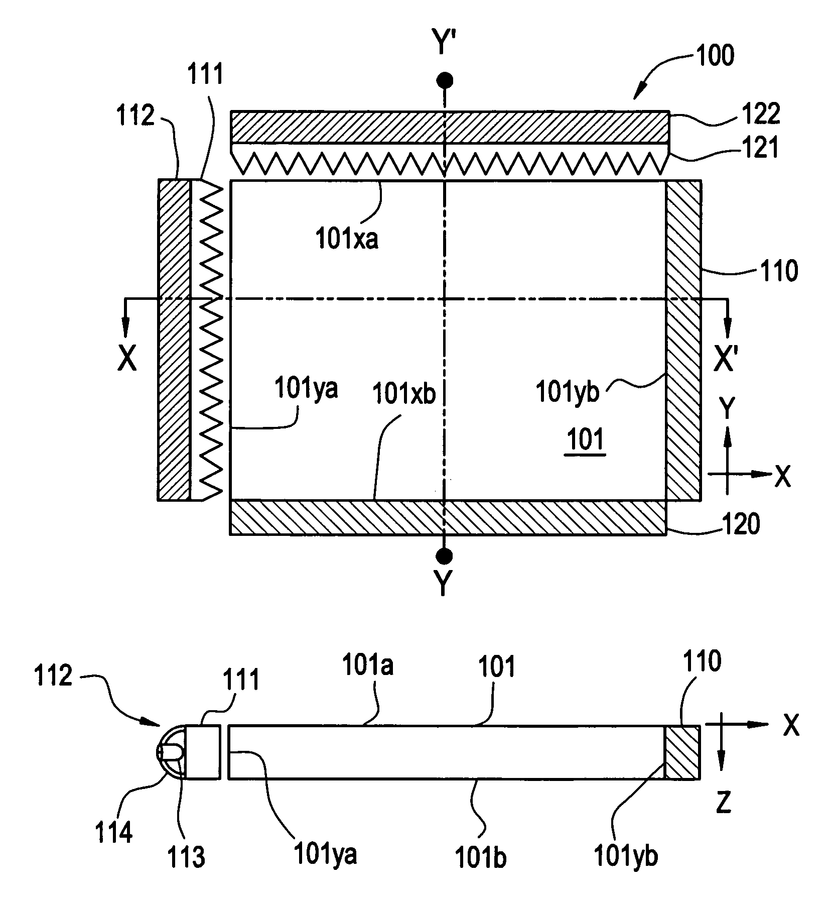
[0029]FIGS. 1A and 1B show the construction of a touch panel of this invention. FIG. 1A is a top view and FIG. 1B is a cross-sectional view of FIG. 1A taken along a dotted line X–X′. In the touch panel 100 of this invention, a panel surface thereof is formed of a light guide panel 101 which is made of translucent material. On a side face 101yb of the light guide panel 101, an optical sensor array 110 for detecting a position in a Y-axis direction (Y coordinates) is closely mounted. A prism lens sheet 111 is mounted on and along a side face 101ya which opposes the side face 101yb and a light emitting face of the prism lens sheet 111 opposes the side face 101ya. Furthermore, an illumination device 112 is provided such that the device 112 opposes to an incident light face of the prism lens sheet 111.

[0030]The cross-sectional structure of the touch panel 10...

second embodiment

[0060]This embodiment is explained in conjunction with FIGS. 4A and 4B. Same constitutional elements used in FIGS. 1A, 1B, FIGS. 2A, 2B and FIGS. 3A, 3B, 3C are denoted by the same numerals. FIGS. 4A and 4B are composed of views showing the construction of a touch panel of this invention, wherein FIG. 4A is a top view and FIG. 4B is a cross-sectional view of FIG. 4A taken along a dotted line X–X′ of FIG. 4A.

[0061]This embodiment is a modification of the first embodiment. This embodiment is characterized by an improvement that it is constructed such that a light led to a light guide panel 101 is efficiently received by optical sensor arrays 110, 120. That is, a pair of prism lens sheets 301, 302 are inserted between the light guide panel 101 and the optical sensor array 110, while a pair of prism lens sheets 303, 304 are inserted between the light guide panel 101 and the optical sensor array 120.

[0062]The prism lens sheets 301, 303 are closely mounted on the side faces 101yb, 101xb o...

third embodiment

[0067]This embodiment relates to a display device equipped with the touch panel of the first or second embodiment.

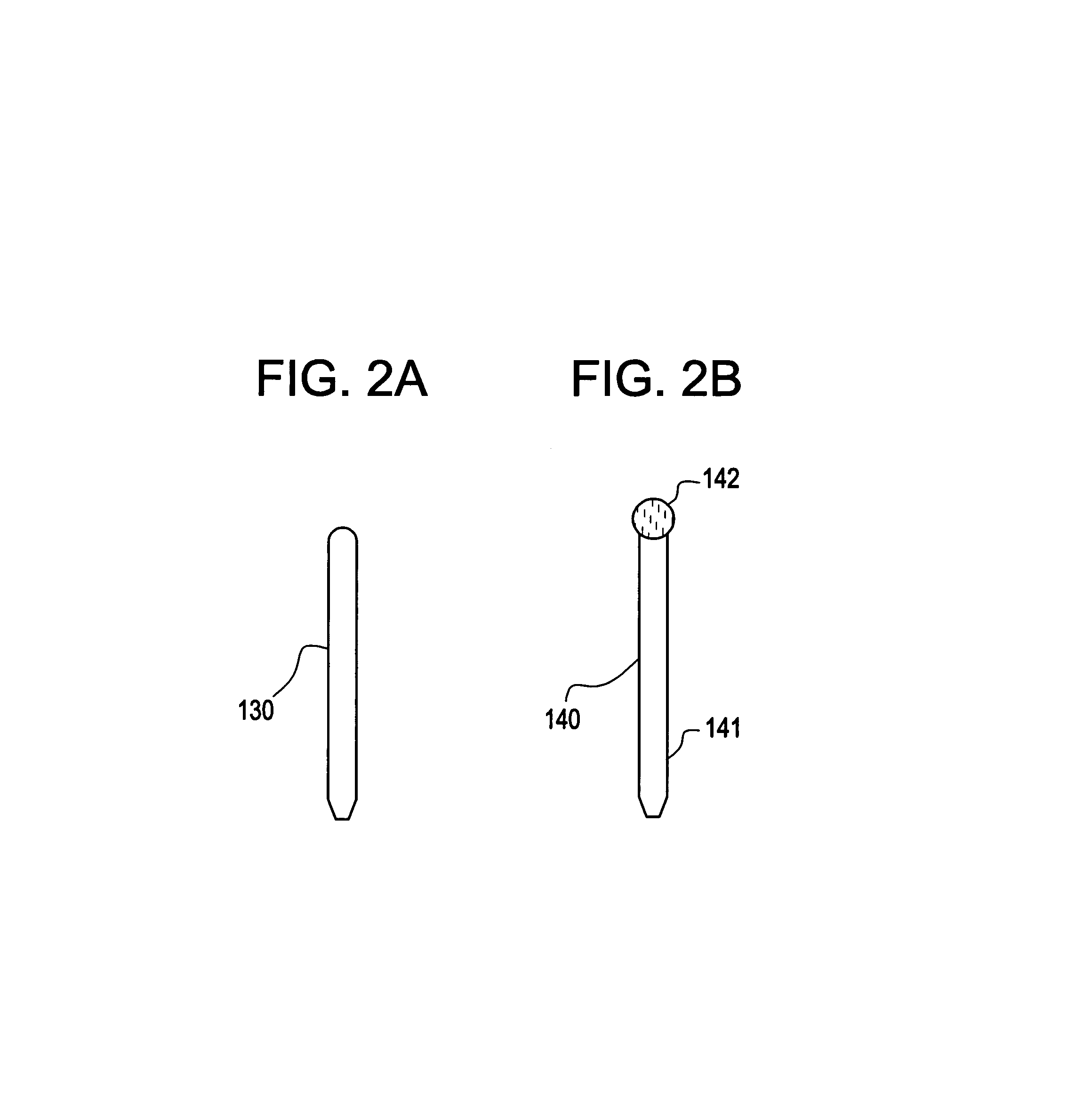
[0068]As shown in FIG. 5, the touch panel 100 of this invention is used in such a manner that it is mounted in front of a display screen of a display device such as a crystal display device 400. Since the light guide panel 101 is made of translucent material, the display screen 401 can be seen by way of the light guide panel 101. When one inputs a character or a picture to the touch panel 100 using the input pen 130 while watching the display screen 401, the screen of the crystal display device is changed corresponding to the change of the position of the input pen 130. When inputting is made using the input pen 130 or the fingertip, substantially no deformation occurs on the light guide panel 101 and hence, no physical force is applied to the screen of the crystal display device below the touch panel.

[0069]It is needless to say that as the display device of this embodim...


PUM


Abstract

A touch panel using an optical sensor has a simple construction and can accurately detect an input position. An illuminating lights emitted from illuminating means are turned into lights having a high directivity in an X-axis direction and in a Y-axis direction of the prism lens sheet and thereafter enter from side faces of a light guide panel as incident lights. The incident lights advance in the inside of the light guide panel toward opposite side faces while being subjected to a total reflection and are received by the optical sensor arrays. When an input pen or a fingertip touches a surface of the light guide panel, the lights are refracted or absorbed at a touched position and hence, a quantity of received lights at the optical sensor arrays is reduced.

Description

BACKGROUND OF THE INVENTION[0001]1. Field of the Invention[0002]This invention relates to a touch panel which detects an input position inputted by a nib of a pen or a fingertip by means of optical sensors and an electronic equipment provided with such a touch panel.[0003]2. Description of the Related Art[0004]Conventionally, a touch panel is provided with pressure sensitive type sensors or electrostatic capacity type sensors on an entire panel surface and when the panel surface is touched with the nib or the fingertip, the sensors detect the position of the nib or the fingertip. Such a touch panel, however, requires mounting of sensors on the entire panel surface so that manufacturing of the touch panel is difficult and there also exists a problem in terms of its mechanical strength.[0005]As a touch panel which can solve the above-mentioned problems, an optical type (or a photoconductive type) touch panel which disposes light emitting elements and light receiving elements on the pe...

Claims


Application Information

Patent Timeline
IPC IPC(8): G09G5/00
CPCG06F3/0421G06F3/0428
Inventor KIMURA, HAJIMEKOYAMA, JUNYAMAZAKI, SHUNPEI
Owner SEMICON ENERGY LAB CO LTD
Why Eureka
Try Eureka