Laser-produced plasma EUV light source with pre-pulse enhancement

a plasma euv light source and laser-produced technology, applied in plasma techniques, x-ray tubes, nuclear engineering, etc., can solve the problem of insufficient pre-pulse intensity to produce efficient euv radiation emissions, achieve improved laser absorption of main laser pulses, reduce target density, and increase euv radiation emissions

Inactive Publication Date: 2005-12-06
UNIV OF CENT FLORIDA RES FOUND INC
View PDF4 Cites 60 Cited by
  • Summary
  • Abstract
  • Description
  • Claims
  • Application Information

AI Technical Summary

Benefits of technology

[0012]In accordance with the teachings of the present invention, an EUV radiation source is disclosed that employs a low energy laser pre-pulse immediately preceding a high energy laser main pulse. The pre-pulse generates a weak plasma in the target area that reduces target density and improves laser absorption of the main laser pulse to increase EUV radiation emissions. The pre-pulse intensity is not great enough to produce efficient EUV radiation emissions. High energy ion flux is reduced by collisions in the localized target vapor cloud generated by the pre-pulse, and thus is less likely to damage source collection optics.

Problems solved by technology

The pre-pulse intensity is not great enough to produce efficient EUV radiation emissions.

Method used


Image

  • Laser-produced plasma EUV light source with pre-pulse enhancement
  • Laser-produced plasma EUV light source with pre-pulse enhancement
  • Laser-produced plasma EUV light source with pre-pulse enhancement

Examples


Embodiment Construction

[0018]The following discussion of the embodiments of the present invention directed to an EUV radiation source employing a laser pre-pulse and a laser main pulse is merely exemplary in nature, and is in no way intended to limit the invention or its application or uses. For example, the pre-pulse technique of the invention may be applicable to other radiation source for generating other wavelengths of light other than EUV.

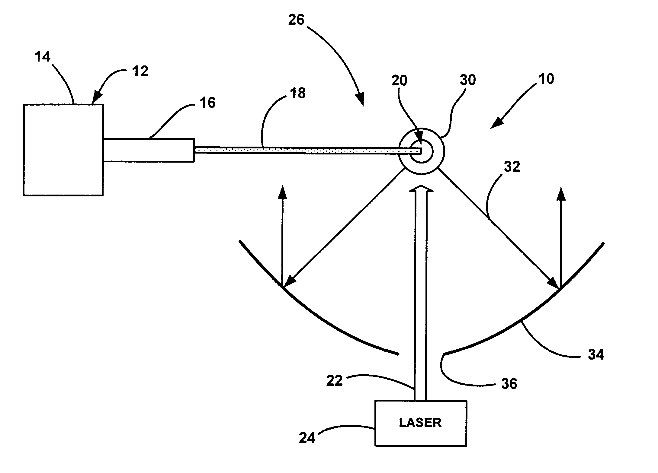
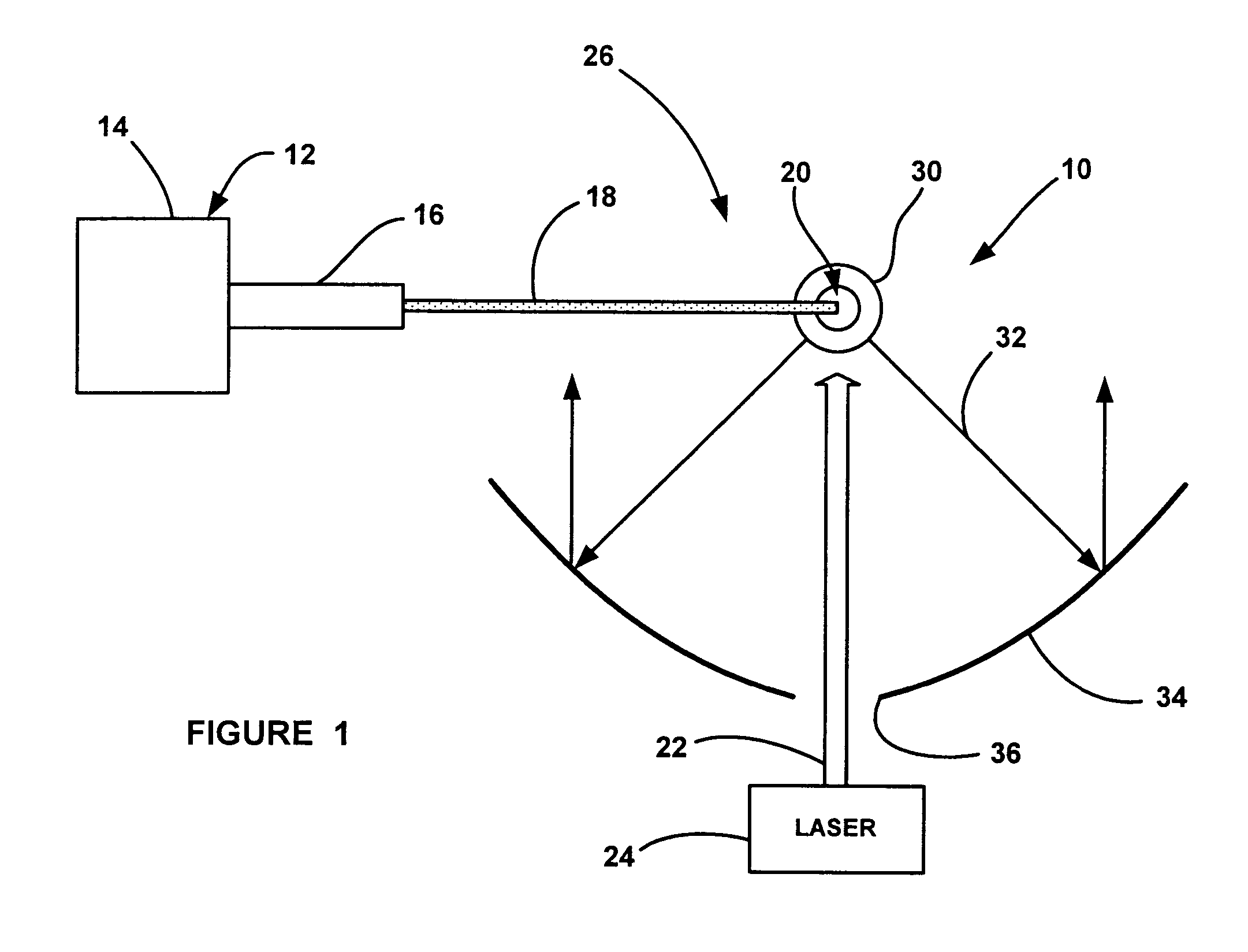
[0019]FIG. 2 is a plan view of an EUV radiation source 50, according to an embodiment of the present invention. As will be discussed in detail below, the EUV radiation source 50 employs a laser pre-pulse beam 52 and a laser main pulse beam 54 that are directed towards a target area 56. In one embodiment, the durations of the pre-pulse beam 52 and the main pulse beam 54 are within the range of 5–30 ns. However, this is by way of a non-limiting example in that any pulse duration suitable for the purposes described herein can be employed. As discussed above, a stream 6...


PUM


Abstract

An EUV radiation source that employs a low energy laser pre-pulse and a high energy laser main pulse. The pre-pulse generates a weak plasma in the target area that improves laser absorption of the main laser pulse to improve EUV radiation emissions. High energy ion flux is reduced by collisions in the localized target vapor cloud generated by the pre-pulse. Also, the low energy pre-pulse arrives at the target area 20–200 ns before the main pulse for maximum output intensity. The timing between the pre-pulse and the main pulse can be reduced below 160 ns to provide a lower intensity of the EUV radiation. In one embodiment, the pre-pulse is split from the main pulse by a suitable beam splitter having the proper beam intensity ratio, and the main pulse is delayed to arrive at the target area after the pre-pulse.

Description

BACKGROUND OF THE INVENTION[0001]1. Field of the Invention[0002]This invention relates generally to an extreme ultraviolet (EUV) radiation source and, more particularly, to a laser-plasma EUV radiation source that employs a low energy laser pre-pulse immediately preceding a high energy laser main pulse to improve the conversion of laser power to EUV radiation.[0003]2. Discussion of the Related Art[0004]Microelectronic integrated circuits are typically patterned on a substrate by a photolithography process, well known to those skilled in the art, where the circuit elements are defined by a light beam propagating through a mask. As the state of the art of the photolithography process and integrated circuit architecture becomes more developed, the circuit elements become smaller and more closely spaced together. As the circuit elements become smaller, it is necessary to employ photolithography light sources that generate light beams having shorter wavelengths. In other words, the resol...

Claims


Application Information

Patent Timeline
Patent Type & Authority Patents(United States)
IPC IPC(8): G21K5/02G21K5/00H01L21/027H05G2/00H05H1/24
CPCH05G2/003H05G2/008
Inventor HARTLOVE, JEFFREY S.MICHAELIAN, MARK E.SHIELDS, HENRYTALMADGE, SAMUELFORNACA, STEVEN W.MARTOS, ARMANDO
Owner UNIV OF CENT FLORIDA RES FOUND INC
Why Eureka
Try Eureka