

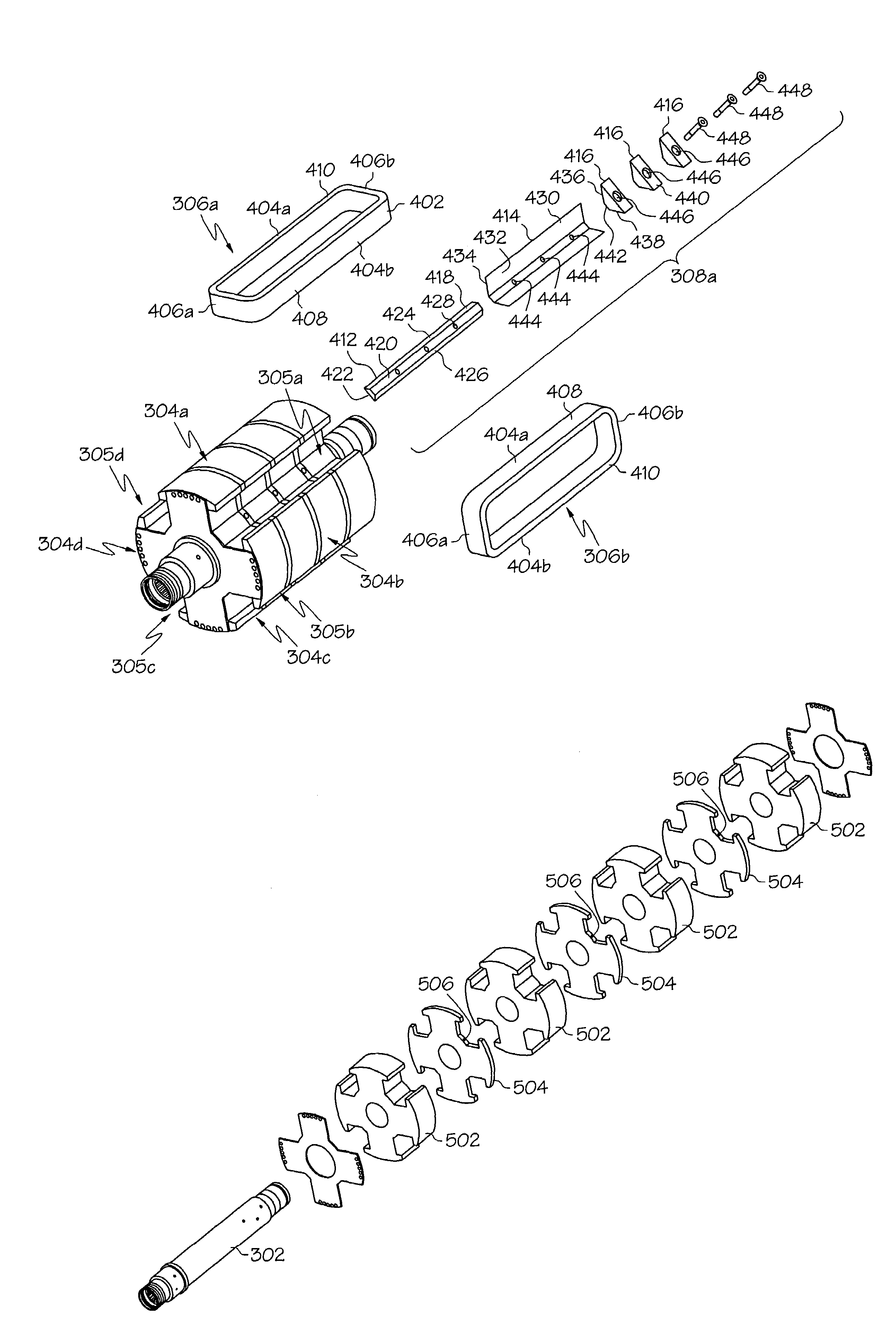
High speed generator with rotor coil support assemblies secured to interlamination disks
a generator and interlamination disk technology, applied in the direction of windings, magnetic circuit rotating parts, magnetic circuit shapes/forms/construction, etc., can solve the problems of large centrifugal forces imposed on the rotors of the generator, affecting the reliability of the generator, inefficiency in the operation of the generator, etc., to achieve the effect of increasing the overall reliability of the generator and less likely to cause damage and/or imbalance in the rotor
- Summary
- Abstract
- Description
- Claims
- Application Information
AI Technical Summary
Benefits of technology
Problems solved by technology
Method used
Image

Examples
Embodiment Construction
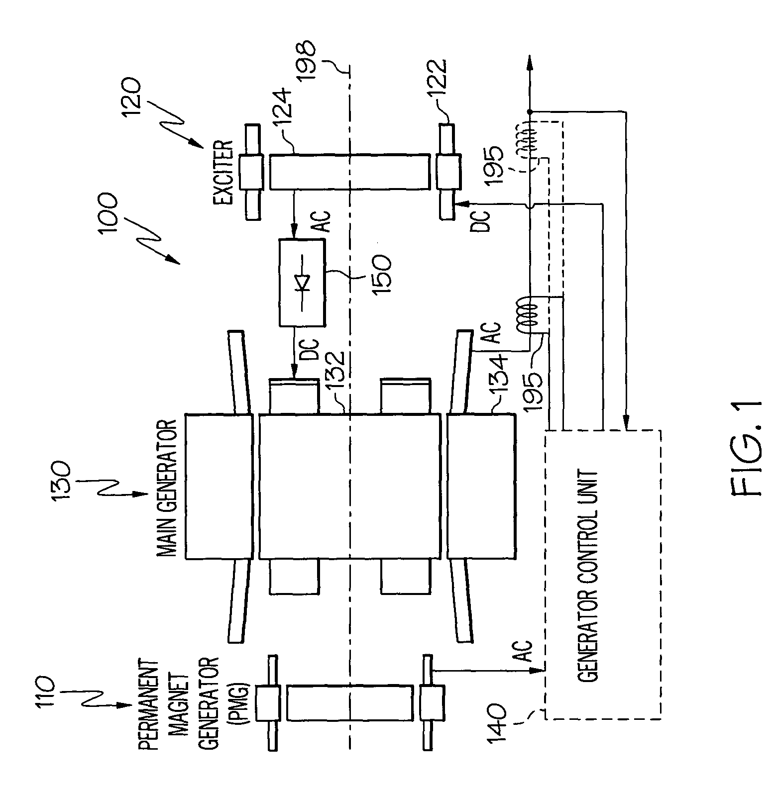
[0020]Before proceeding with the detailed description, it is to be appreciated that the present invention is not limited to use in conjunction with a specific type of electrical machine. Thus, although the present embodiment is, for convenience of explanation, depicted and described as being implemented in a brushless AC (alternating current) generator, it will be appreciated that it can be implemented in other AC generator designs needed in specific applications.
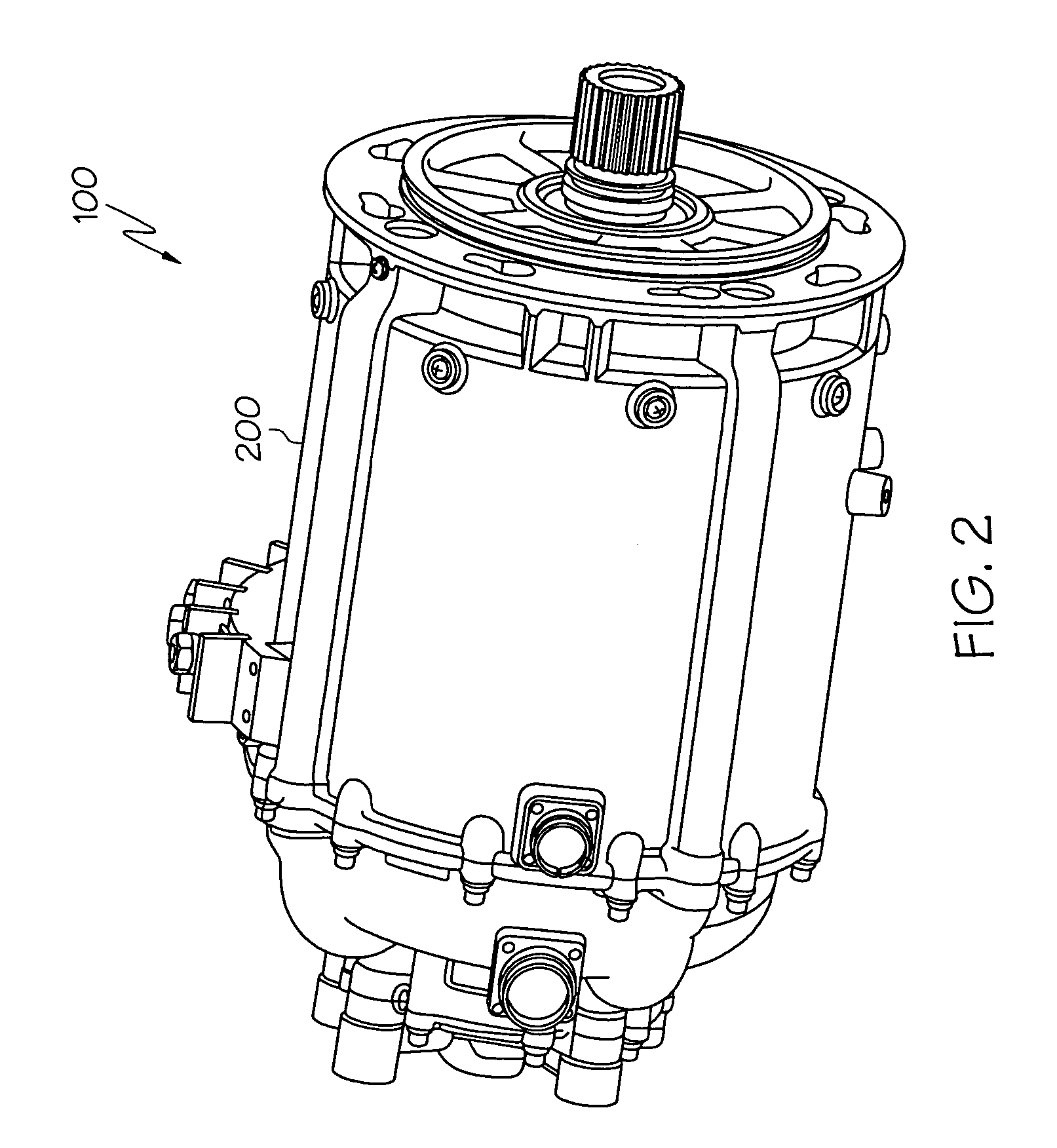
[0021]Turning now to the description, and with reference first to FIG. 1, a functional schematic block diagram of an exemplary high speed generator system 100 for use with a gas turbine engine such as that in an aircraft is depicted. This exemplary generator system 100, which is commonly known as a brushless AC generator, includes a permanent magnet generator (PMG) 110, an exciter 120, a main generator 130, a generator control unit 140, and one or more rectifier assemblies 150. During operation, a rotor 112 of the PMG 110, ...
PUM
 Abstract
Description
Claims
Application Information