
Method and assembly for operating and/or observing a device that monitors an industrial controller

a technology of industrial controllers and assembly methods, applied in the direction of electric controllers, program control, instruments, etc., can solve the problems of reducing the installation work involved in changing the plant structure and/or control structure, and achieve the effect of convenient us

Inactive Publication Date: 2005-12-06
SIEMENS AG
View PDF26 Cites 7 Cited by
  • Summary
  • Abstract
  • Description
  • Claims
  • Application Information

AI Technical Summary

Benefits of technology

[0008]With this measure, the user interface of the connected monitoring client computers is no longer controlled locally but via the network, by an interface module that is installed in the server computer or in a device directly connected thereto. As a result, the information on the current state of the user interfaces of all the active client computers is relocated to the server computer. Upon request by an operator, the user interface currently set up on an operator unit can therefore be transferred immediately to another operator unit. In addition, the information on the plant structure and / or control structure required to set up the user interfaces is preferably also relocated to the interface module according to the invention, which is installed in the area of the server. As a result, when these same structures are changed, only the interface module or the data it uses needs to be changed. This can be done in a single step together with the change in the actual monitoring function block of the respective server computer. This significantly reduces the installation work involved in changing the plant structure and / or control structure. At the same time, the activities to be carried out by a client computer are minimized, i.e., to the relaying of information from the higher-level server computer to a display screen on the one hand and the information that is entered by an operator to the server computer on the other. Because the client computer uses separate input / output modules—e.g., display screens, keyboard, mouse—the actions to be carried out by the actual client computer are so simple that the minimum program that is still required for this purpose can easily be designed to run with a wide variety of operating systems. For this reason and because of the reduced client computer hardware requirements, a user is able to fall back on inexpensive offers for this purpose. Furthermore, there is no risk that such client computers become quickly obsolete—a typical occurrence in the computer industry—because the more complex computing tasks are performed exclusively in the server computer.
[0023]Furthermore, when the starting address associated with the additional program is called, an additional management data record is created for the newly logged-on operator unit and, if necessary, a memory area is assigned to it. When an additional client computer logs on, after the interface function block according to the invention has been set up in the previous step if required, a management data record associated with this additional client computer is created and, if required, a memory area is reserved as an information buffer. Such a memory area can have, for example, the size of a bitmap if the server computer takes over the entire screen display of the client computer. This enables the function block according to the invention to perform other tasks during the transmission of the picture data thus determined, so that fast simultaneous operation serving a plurality of client computers is made possible.

Problems solved by technology

This significantly reduces the installation work involved in changing the plant structure and / or control structure.

Method used


Image

  • Method and assembly for operating and/or observing a device that monitors an industrial controller
  • Method and assembly for operating and/or observing a device that monitors an industrial controller
  • Method and assembly for operating and/or observing a device that monitors an industrial controller

Examples


Embodiment Construction

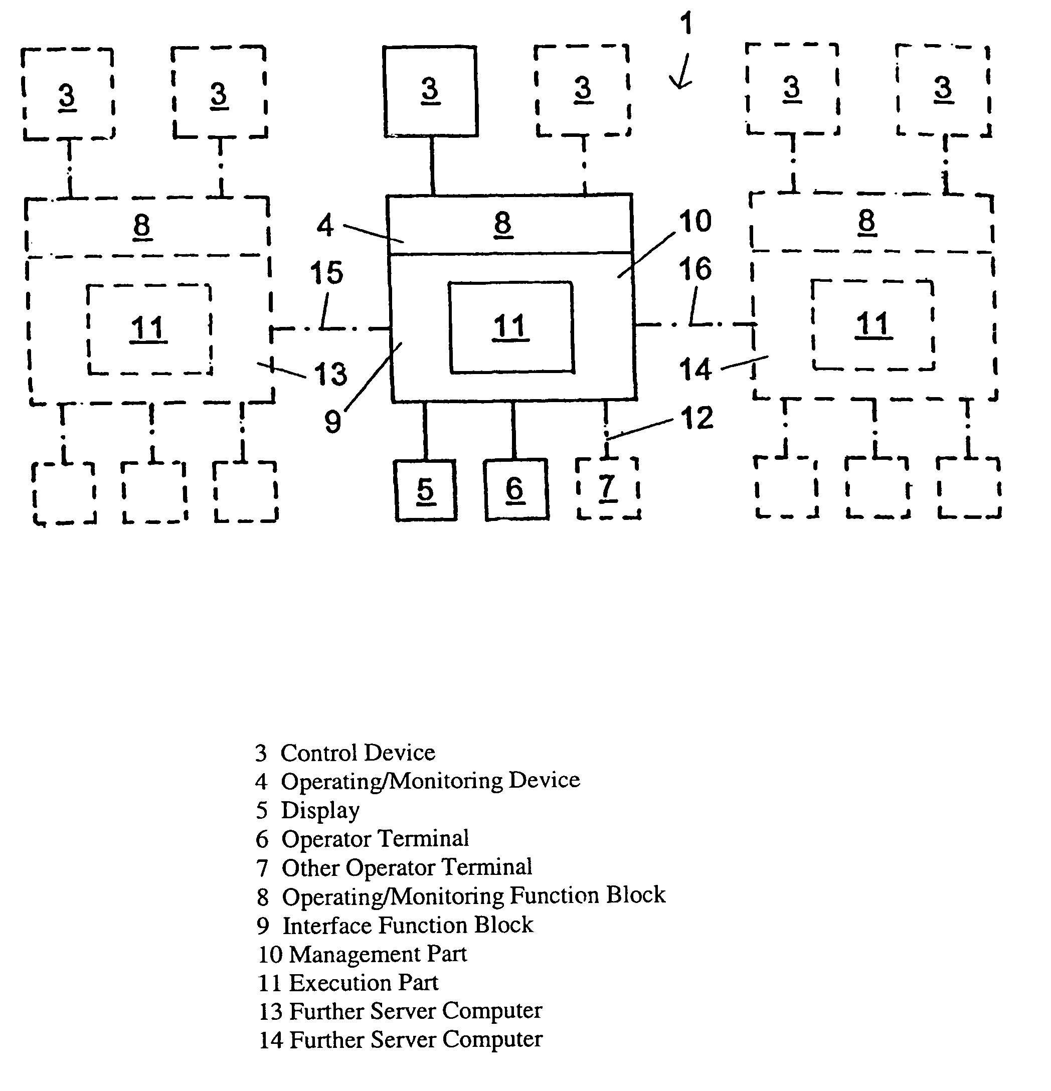
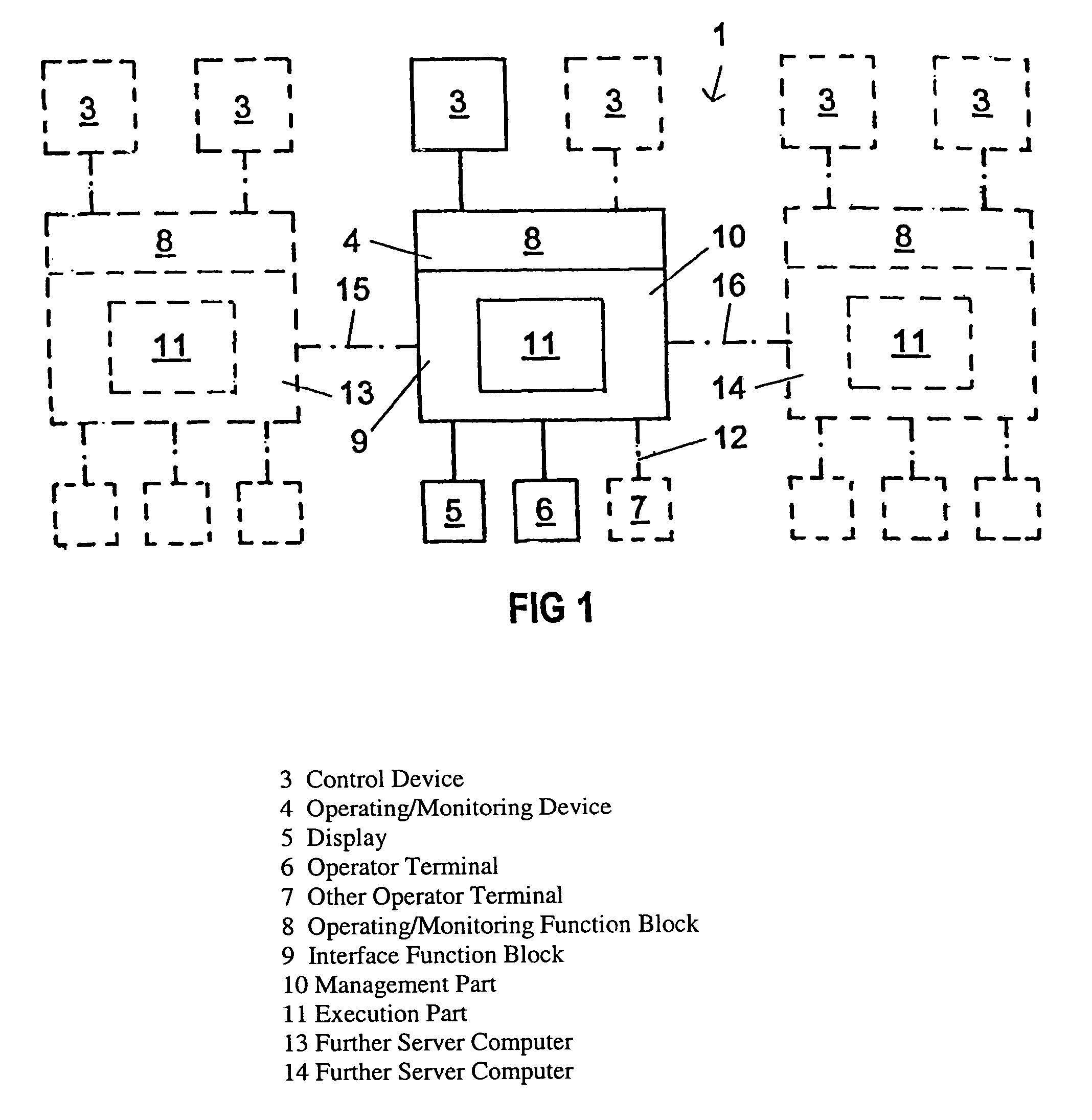
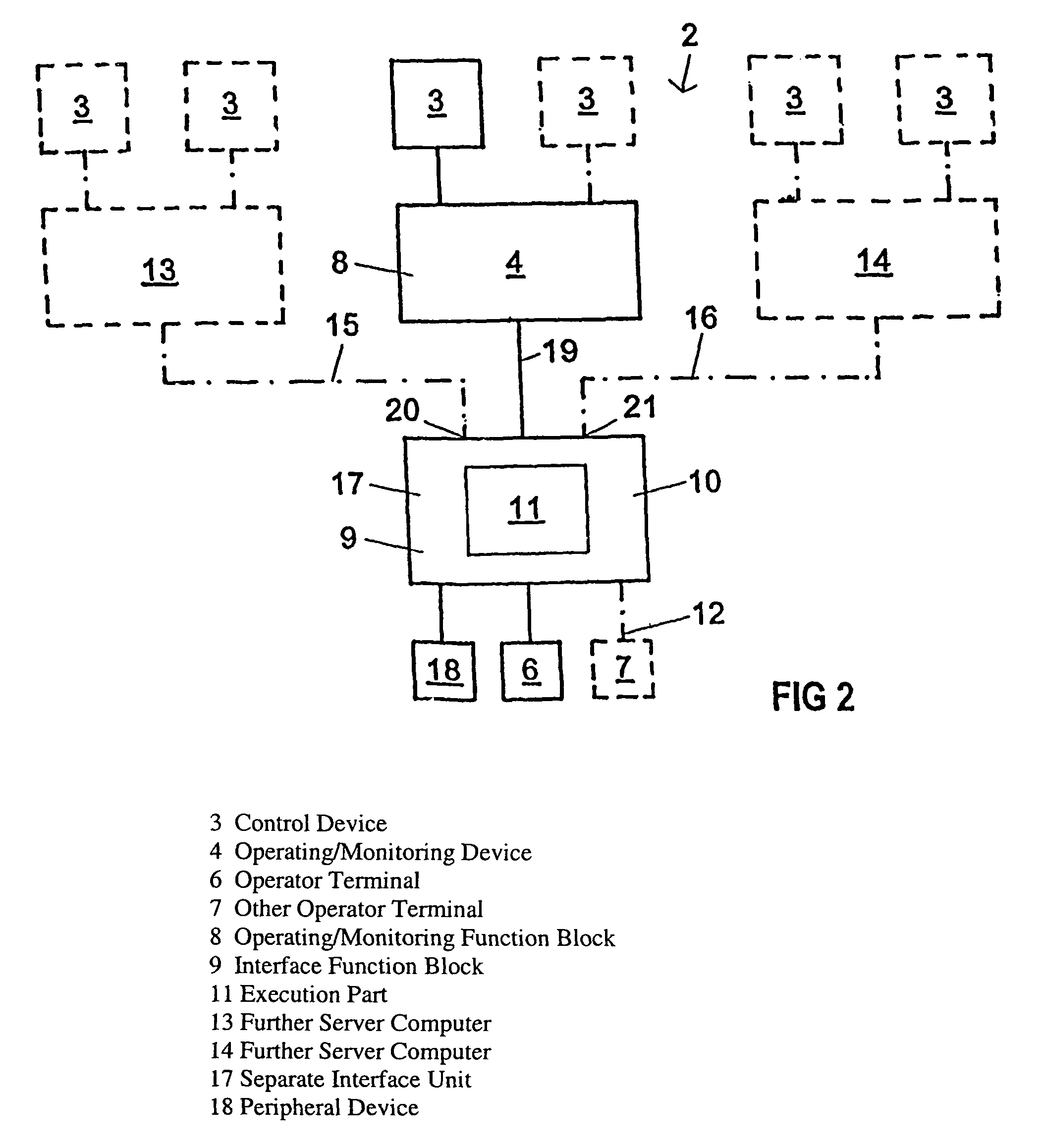
[0034]The two drawing figures show different network structures 1, 2 in which the invention is advantageously incorporated. The part of the circuit drawn with solid lines corresponds to a minimal configuration while the dash-dotted lines indicate optional units.

[0035]In the minimal configuration according to FIG. 1, at least one control device 3 is provided for controlling a plant part in accordance with an internal program. The respective state of the plant part can be determined with an operating and / or monitoring device 4 and can be displayed for the control personnel, for example on a display screen 5 connected thereto. In addition, at least one operator terminal 6 remote from the operating and / or monitoring device 4 is provided, with which the same functionality can be realized at a remote location as with the input and / or output means 5 of the operating and / or monitoring device 4 itself. In order to be able to communicate without interference from this operator terminal 6 and ...


PUM


Abstract

A system for operating / observing a monitoring device of a process controller device of / in a remote operator unit. An additional function block is provided in / on the monitoring device, which intervenes in the communication between the monitoring device and the connected operator units, at least partially takes over the functions that are to be executed by one or more of the operator units and processes the information to be displayed on the operator unit in such a way that the information can be directly displayed.

Description

[0001]This application is a Continuation of International Application PCT / EP02 / 028 11, with an international filing date of Mar. 13, 2002, which was published under PCT Article 21(2) in German, and the disclosure of which is incorporated into this application by reference; this application is additionally a Continuation-In-Part of U.S. application Ser. No. 09 / 812,205, filed Mar. 13, 2002.FIELD OF AND BACKGROUND OF THE INVENTION[0002]The invention relates to a method and an assembly for operating and / or observing a device for monitoring at least one controller, coupled with an installation or process, of / in at least one remote operator unit that communicates with the monitoring device.[0003]The capacity of computers continues to increase and open up new applications in the field of industrial control and monitoring systems. As a result, monitoring tasks are increasingly delegated to programmable controllers. Whereas initially only isolated parts in industrial production plants were a...

Claims


Application Information

Patent Timeline
IPC IPC(8): G05B15/02G05B23/02
CPCG05B15/02G05B23/0213G05B23/0272G05B2219/13G05B2223/06
Inventor BIEBER, JUERGEN
Owner SIEMENS AG
Learn More