
Method and system for simulating execution of a target program in a simulated target system

a target system and target program technology, applied in the field of embedded system testing and development, can solve the problems of strict integration problems, the target program loaded at the time of the integration of the prototype target hardware and software does not work, and the embedded system has become very complex

Inactive Publication Date: 2005-12-06
NXP USA INC
View PDF64 Cites 110 Cited by
  • Summary
  • Abstract
  • Description
  • Claims
  • Application Information

AI Technical Summary

Problems solved by technology

With the advent of 32-bit microprocessors and complex operating software, embedded systems have become very complex systems.
However, when a program developer begins work on the target program, the physical target hardware which will ultimately execute the target program is usually under development and does not exist.
Because of the prior unavailability of the actual target hardware, one often finds that the target program loaded at the time of the integration of the prototype target hardware and software does not work.
It is common to find that the integration problems are strictly due to software complications alone.
This may cause significant delays in the software development due to the problems in the target program.
Other problems with the integration may be caused by the interaction of the target hardware with the target program.
Consequently, considering the large cost of ASIC and custom IC design, and the relatively low cost ease of software modification, it is common that the software will be force-fitted to the target hardware prototype, thereby increasing the overall planned software development time.
Problems associated with the interaction between the target hardware and the target program can be detected and corrected before final hardware fabrication, often saving costly and time-consuming redesign of the ASIC.
Although the hardware simulator can provide valuable information to a software developer, there are disadvantages in using the hardware simulator to simulate the target hardware.
The full-functional processor model can be extremely detailed for a complex circuit, such as the target processor, and thus difficult to model.
The resulting simulation may be very accurate; however, the level of detail comes at the cost of lengthy simulation times. The execution time required to simulate the full-functional processor model can add significantly to the simulation run-times because the hardware simulator must simulate all activity that occurs in the target processor using the processor functional model to detect timing errors, race conditions, and the like.
The additional burden of trying to run longer simulation required for larger target programs into the processor memory model can consume large amounts of system resources, and simulation run time can become unacceptably long.
Although this method provides accurate estimated execution times, the process is very time consuming.
A typical software program has several of these types of loops, resulting in a very lengthy process for calculating a total estimated execution time.
The consequence is an inefficient use of resources and time.
Although the static estimation technique provides faster results than for the other simulation methods previously mentioned, this method is only as accurate as the statistical model used to calculate the estimated execution time.
Additionally, there are several limitations with respect to using the static estimation technique for target processors having pipelined processing, instruction pre-fetching, vector processing and caching.

Method used


Image

  • Method and system for simulating execution of a target program in a simulated target system
  • Method and system for simulating execution of a target program in a simulated target system
  • Method and system for simulating execution of a target program in a simulated target system

Examples


Embodiment Construction

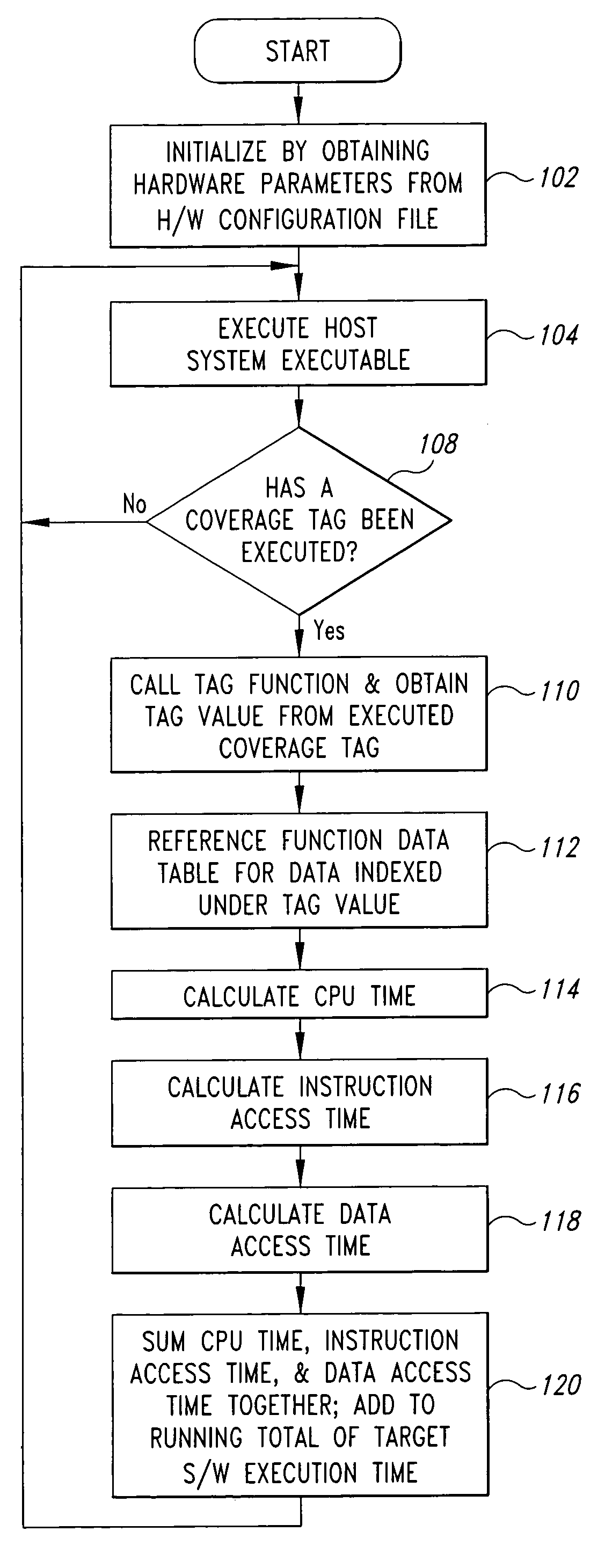
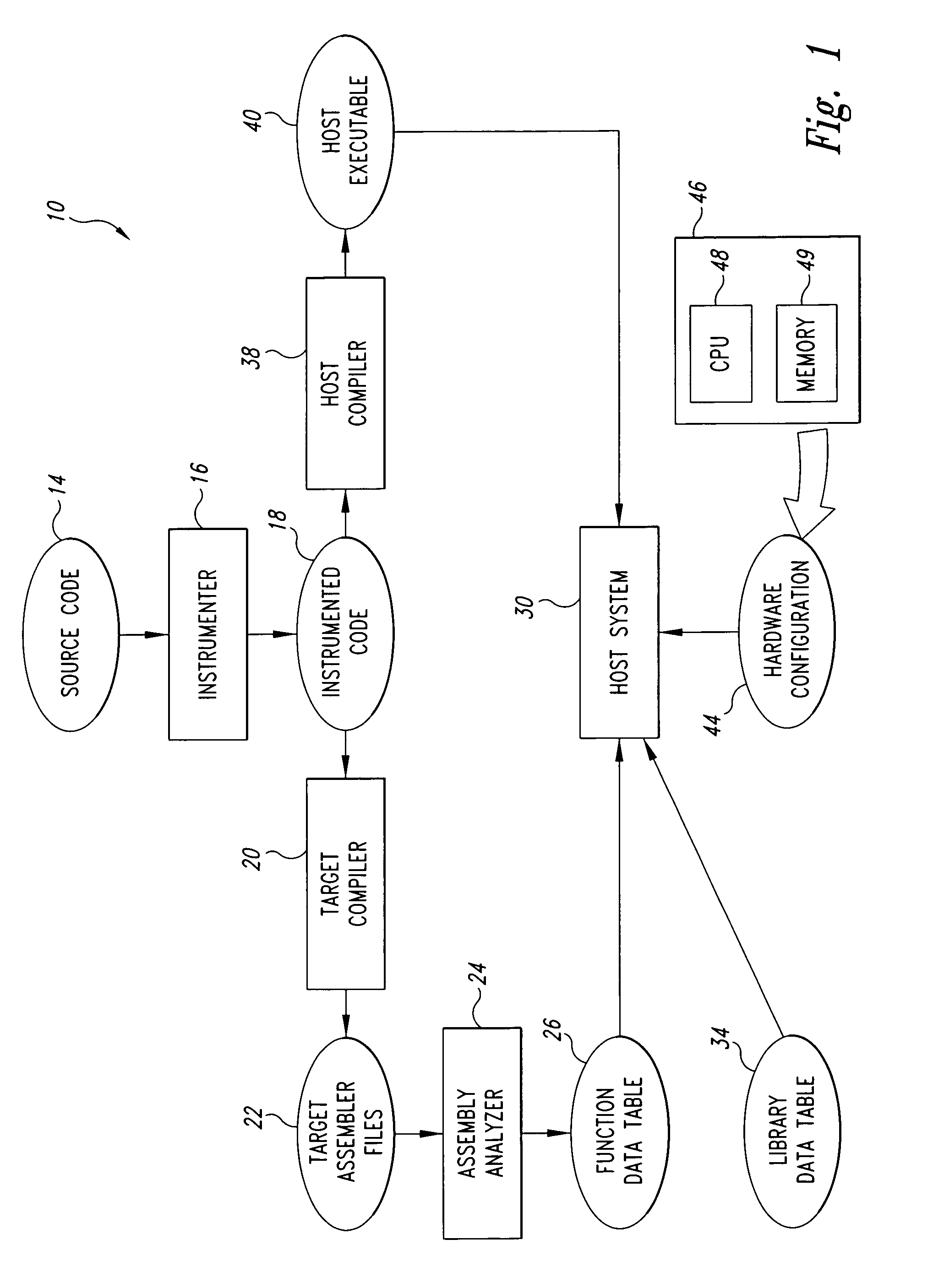
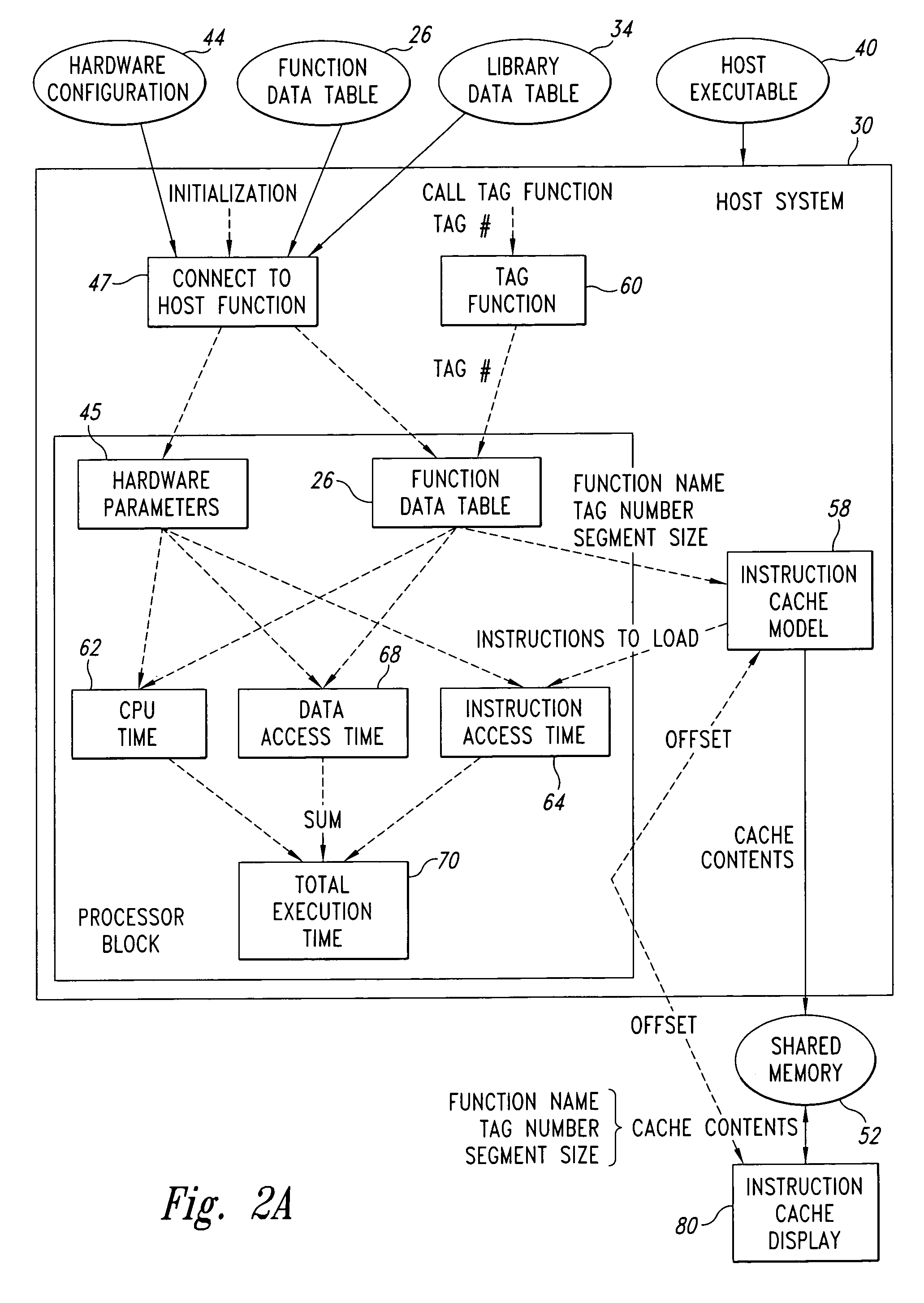
[0021]The disclosed embodiment of the present invention allows for the early simulation of the target hardware and permits the parallel development of the target hardware and the target program. The disclosed system also allows the extensive use of existing debugging tools to aid the developer in the development and integration of the target system. The embodiments of the present invention calculate an estimated target program execution time for a simulated target hardware, as well as maintain an instruction cache image of the simulated target processor. The estimation technique accounts for detailed characteristics of the simulated target processor architecture, such as parallel execution, pipelining, caches, and pre-fetching. The information provided can be used by the software developer to forecast resource requirements, and identify target hardware bottlenecks and resource constraints prior to having the physical target hardware. Although there are conventional hardware simulato...


PUM


Abstract

A method and system for simulating the execution of a software program on a simulated hardware system. An instrumented software program is divided into program segments delineated by tags and is then analyzed for data describing the program segments. The data is tabulated and indexed in a function data table according to the program segments. Hardware parameters that at least define a portion of the simulated hardware system are tabulated in a hardware configuration file. The software program is executed on a host system, and when a tag is executed, data indexed in the function data table under the program segment corresponding to the executed tag and hardware parameters tabulated in the hardware configuration file are used to calculate an estimated execution time for the program segment corresponding to the executed tag. The estimated execution time for the program segment is added to a running total for the overall execution time of the software program. The system includes a memory for storing software parameters describing program segments of the software program, and for storing hardware parameters that at least partially define the simulated hardware system. The system further includes a processor for calculating an estimated execution time for the software program using the software and hardware parameters.

Description

TECHNICAL FIELD[0001]The present invention relates generally to testing and developing the software and hardware of embedded systems, and more specifically, to a system and method for simulating the execution of software in a simulated hardware environment.BACKGROUND OF THE INVENTION[0002]With the advent of 32-bit microprocessors and complex operating software, embedded systems have become very complex systems. An embedded system is a system whose primary purpose is to perform a specific function rather than to perform general computational functions. A microprocessor-based microwave oven controller, a microprocessor-based automobile ignition system, and a microprocessor-based telephone switching system are all examples of embedded systems. An embedded system typically includes a microprocessor, which executes a stored software program and interacts with an application specific integrated circuit (ASIC) or a custom Integrated Circuit (IC). The microprocessor used in the system is de...

Claims


Application Information

Patent Timeline
IPC IPC(8): G06F11/34
CPCG06F11/3457G06F2201/865
Inventor MAXWELL, III, SIDNEY RICHARDSSTEINBERGER, MICHAEL LOUIS
Owner NXP USA INC
Learn More