

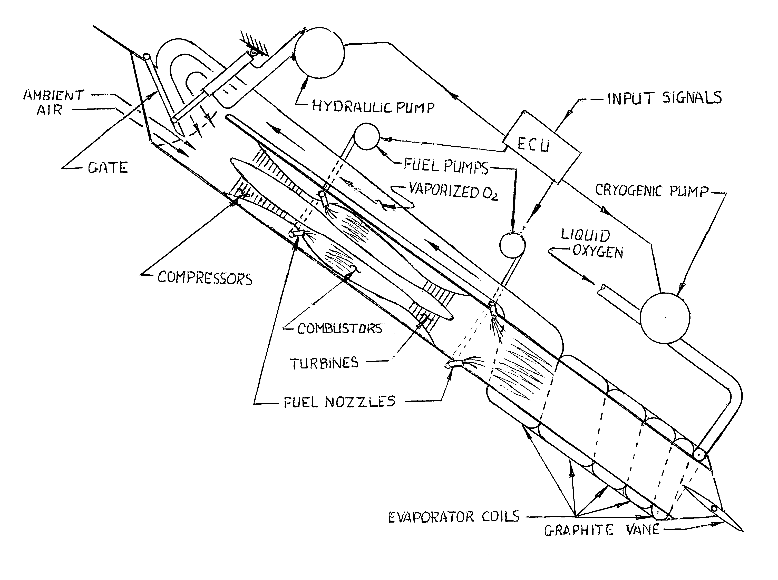
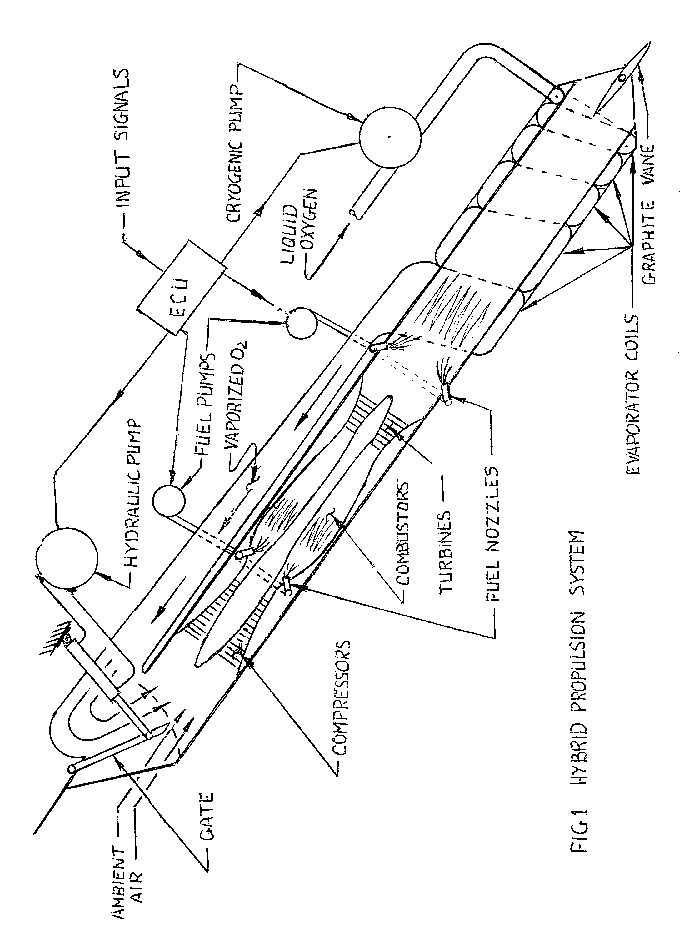
Hybrid propulsion system
a propulsion system and hybrid technology, applied in the field of aerospace propulsion systems, can solve the problem of limited altitude to which an aircraft can ascend
- Summary
- Abstract
- Description
- Claims
- Application Information
AI Technical Summary
Benefits of technology
Problems solved by technology
Method used
Image

Examples
Embodiment Construction
[0005]At the start the system, liquid oxygen is pumped into the evaporator which consists of a helical coil wrapped around the cylindrical after burner. The cross-section of the coil expands progressively to accommodate the expanding oxygen. The evaporator coils stop at the turbine section where it becomes a straight duct on the topside of the engine. The vaporized oxygen now passes through an opening in the top of the rectangular intake and is deflected towards the compressor section of the engine. With the gate setting illustrated in FIG. 1, ambient air is also admitted. The air / oxygen mix passes through the compressors into the combustors where fuel is sprayed in to maintain the flame front. The oxygen rich exhaust stream then enters the after burner where more fuel is added to further increase thrust. As altitude increases the gate gradually closes off the air intake, and the system continues to run on pure oxygen. Beyond the atmosphere, the exhaust stream is vectored for steeri...
PUM
 Abstract
Description
Claims
Application Information