Compact lighting system with improved light transmission and color filters

a technology of which is applied in the field of compact lighting systems with improved light transmission and color filter, can solve the problems of unsatisfactory lighting effect, low percent of light transmission when pastel colors are created, and large lenses are costly, so as to reduce the overall length of the optical path, reduce the size of the image lens, and compact the effect of the lighting modul

Inactive Publication Date: 2005-12-13
RAMBUS DELAWARE
View PDF5 Cites 26 Cited by
  • Summary
  • Abstract
  • Description
  • Claims
  • Application Information

AI Technical Summary

Benefits of technology

[0017]An advantage of the present invention is that positioning the image lens in the smallest portion of the light beam minimizes the size of the image lens required.
[0018]Another advantage of the present invention is that placing the aperture upstream of the filter module reduces the overall length of the optical path, thereby allowing construction of a more compact lighting module.
[0019]A

Problems solved by technology

One drawback of the system disclosed in Richardson is that the percentage of light transmission is low when pastel colors are created.
This factor can lead to an unsatisfactory lig

Method used


Image

  • Compact lighting system with improved light transmission and color filters
  • Compact lighting system with improved light transmission and color filters
  • Compact lighting system with improved light transmission and color filters

Examples


Embodiment Construction

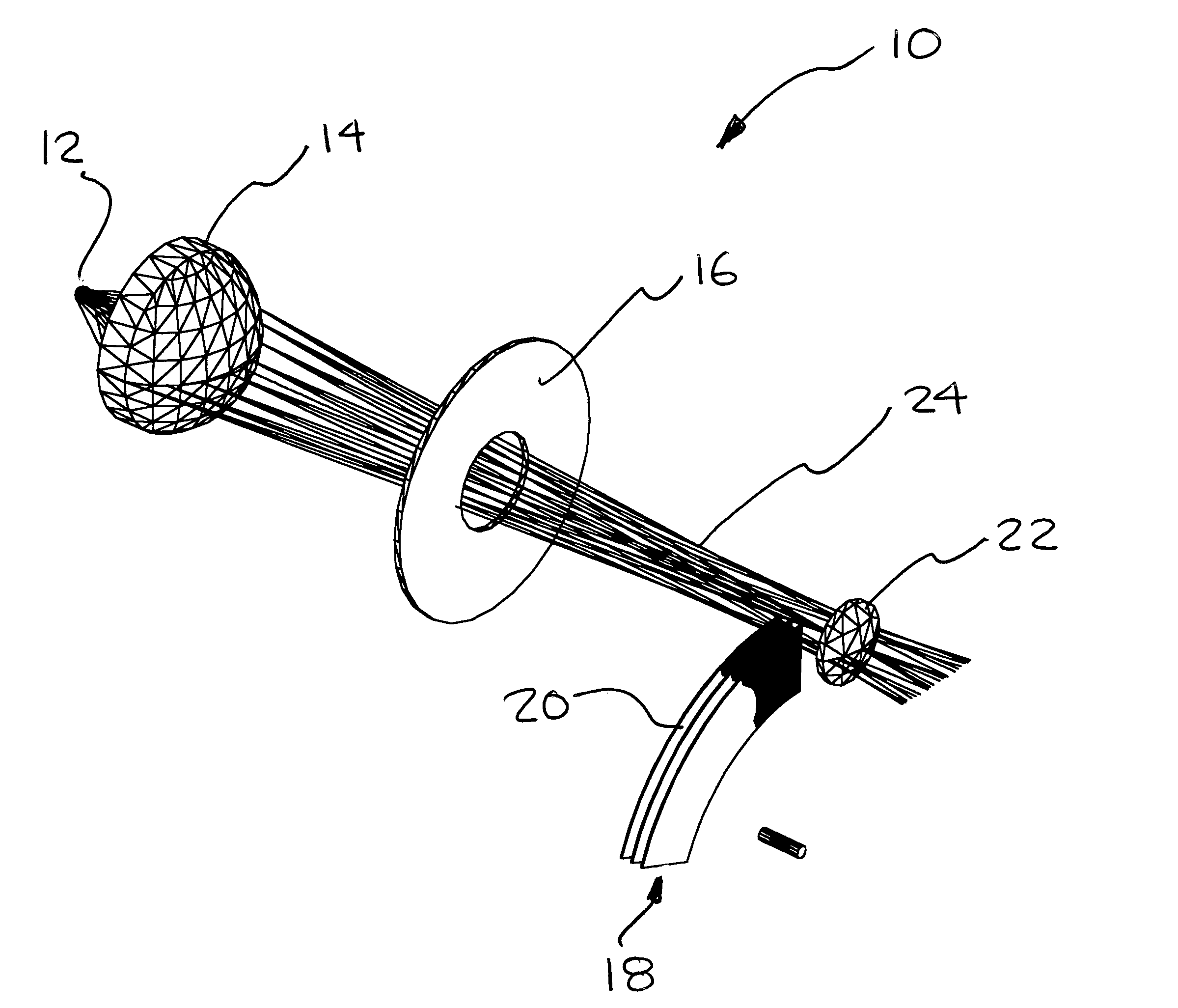
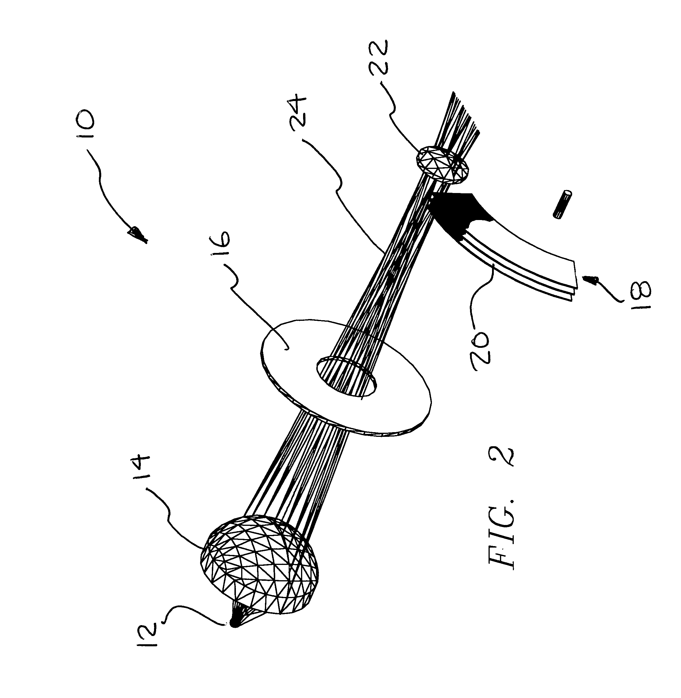
[0037]Referring first to FIGS. 2–4, the present invention is a lighting system 10 that comprises a light source 12, a means of collecting and focusing light 14, an aperture 16, a filter module 18 containing at least one color filter element 20, and an image lens 22.

[0038]The light source 12 can be an incandescent light, an arc lamp, or one or more LED's. A light beam 24 generated by the light source 12 is directed by the means of collecting and focusing light 14. The most commonly utilized means of collecting and focusing light 14 is a condensing lens as is illustrated in FIGS. 2 and 3. Other collecting and focusing means 14 known by those skilled in the art can also be used, such as the elliptical reflector illustrated in FIG. 4.

[0039]After the light beam 24 is directed through the condensing lens 14, the beam 24 passes through an aperture 16. The aperture 16 defines the object of the lighting system 10. After the light beam 24 passes through the aperture 16, it reaches an image le...


PUM


Abstract

A lighting system including a light source, a means of collecting and focusing light from the light source, an aperture, a filter module containing at least one color filter, and an image lens. A light beam from the light source is focused through the aperture to define the image to be projected. The aperture is positioned upstream of the color filter, with the filter and the image lens being deployed in the area of the light beam where the diameter is at a minimum. The filter elements used in the filter module are two stage filters, having a first stage for a pastel level of a particular filter color, and a second stage for a saturated level of the subject color. Each stage has a gradient segment and a solid color segment. The result is a filter element with four regions that blend into each other.

Description

BACKGROUND OF THE INVENTION[0001]1. Field of the Invention[0002]The present invention relates generally to entertainment and architectural lighting, and more specifically is a device to control the hue and saturation of color emanating from a lighting fixture.[0003]2. Description of the Prior Art[0004]Colored light sources are often used in the theater, television, touring productions, and architectural applications. The projected light color is varied in hue, saturation level, beam size, and / or focus to obtain a particular desired artistic effect. The requirements of the effect might be that the color and / or focus remain static, or that the color and / or focus change over time. Factors that must be considered when choosing a color changing lighting system to create various effects are cost, the quantity of colors to be produced, the smoothness of color transition, size and weight of the lighting units, and the efficiency of light transmission through the color filters. The system mu...

Claims


Application Information

Patent Timeline
IPC IPC(8): F21S8/00F21V9/00F21V9/08G02B5/20G02B7/00G02B26/00G02B27/28
CPCF21V9/08G02B5/20G02B26/007F21W2131/406
Inventor RICHARDSON, BRIAN EDWARD
Owner RAMBUS DELAWARE
Why Eureka
Try Eureka