Multifolded composite tape for use in cable manufacture and methods for making same
Inactive Publication Date: 2005-12-13
NEPTCO +1
View PDF18 Cites 24 Cited by
Summary
Abstract
Description
Claims
Application Information
AI Technical Summary
This helps you quickly interpret patents by identifying the three key elements:
Problems solved by technology
Method used
Benefits of technology
Benefits of technology
[0007]According to the invention, a multifolded composite tape is provided to better facilitate isolation and electrostatic shielding of multiple pairs of insulated conductors of a high-speed data transmission cable that is required to meet the need for greater speed, throughput and quality of signal and data transmission. The multifolded composite tape of the invention is constructed as a single tape configuration having a robust shielding construction to compartmentalize and encapsulate individual pairs of insulated conductors (referred to herein as “twisted pairs”) during cable manufacture. The composite tape of the invention has the benefit of using a single tape configuration that completely wraps, electrically shields, and isolates individual twisted pairs to achieve a desired crosstalk performance.
[0008]The multifolded composite tape of the invention resolves many of the problems associated with individually wrapping twisted pairs, to achieve greater consistency of electrical properties and electrical performance. In addition, the various single tape configurations of the invention increase manufacturing productivity by reducing the amount of tape required to wrap individual twisted pairs and increasing production speed. In addition, the single tape configurations provide greater strength, thereby reducing the incidence of tape break during cable manufacture. The single tape design also provides a more consistent geometry that imparts consistency and predictability with respect to electrical properties and cable performance.
[0012]Each channel or groove is of sufficient size to lay at least one twisted cable therein. During cable manufacturing, four twisted pairs are laid in the X-shaped single tape configuration and therein simultaneously wrapped by utilizing one or more forming dies. The foil layer facing each channel or groove essentially provides a continuous, longitudinal foil-to-foil wrap in which a twisted pair is encapsulated. The foil-to-foil wrap physically separates and electrically shields the twisted pair by achieving a continuous and closed conductive shield. The resultant foil-to-foil contact achieved avoids the problems associated with foil-to-film overlap produced during individually wrapping twisted pairs.
[0013]In a second embodiment of the invention, a single tape configuration comprises at least one metallic foil / film laminate accordion-folded to form a single tape configuration having a cross-section or profile that forms or defines one or more channels or grooves extending longitudinally along a length of the single tape. The metallic foil / film laminate is similarly constructed as described above with respect to the foil / film laminates of the first embodiment. The metallic foil / film laminate is accordion-folded lengthwise into a multiple of pleats to achieve a single tape configuration having an accordion cross-section or profile. Each pleat can be of a substantially equal width. Each pleat includes a foil layer on a first side and a film layer on a second opposite side. During formation of the multiple of accordion pleats, each pleat having the film layer folded therein is fused or bonded to seal the pleat. The foil / film laminate is accordion-folded lengthwise until a desired number of pleats is achieved. The number of pleats created is related to the number of channels or grooves required. Thereafter, the single tape configuration is opened by unfolding the pleats having the foil layer folded therein and wrapping the single tape back upon itself such that the foil layer is oriented to face or define one or more channels or grooves. The single tape configuration which results comprises two or more fin-like shield members extending radially from a center axis or vertical center line and longitudinally along the length of the single tape to form or define the one or more channels or grooves. The single tape configuration of the second embodiment provides, the flexibility to provide as many channels and grooves as may be required to wrap any number of twisted pairs contained within a particular cable design.
Problems solved by technology
This transfer of electrical energy between twisted pairs is a phenomenon known as crosstalk, which interferes and degrades electrical signals and data transmission.
Crosstalk presents a particular problem in high frequency applications wherein as the frequency of transmission increases, crosstalk increases logarithmically.
Such overlaps are susceptible to signal leakage, interference and signal degradation as well as contribute to crosstalk between adjacent twisted pairs and proximate cables.
In addition, individually wrapping twisted pairs is a lengthy operation and an additional step in manufacturing twisted pairs.
Method used
Image
Click on the blue label to locate the original text in one second.
Reading with bidirectional positioning of images and text.
Examples
first embodiment
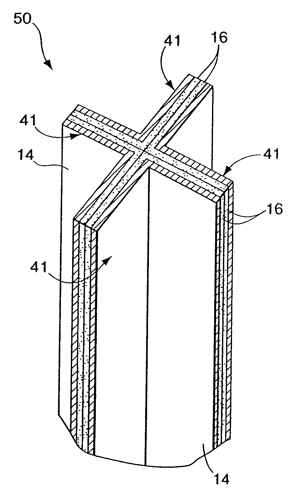
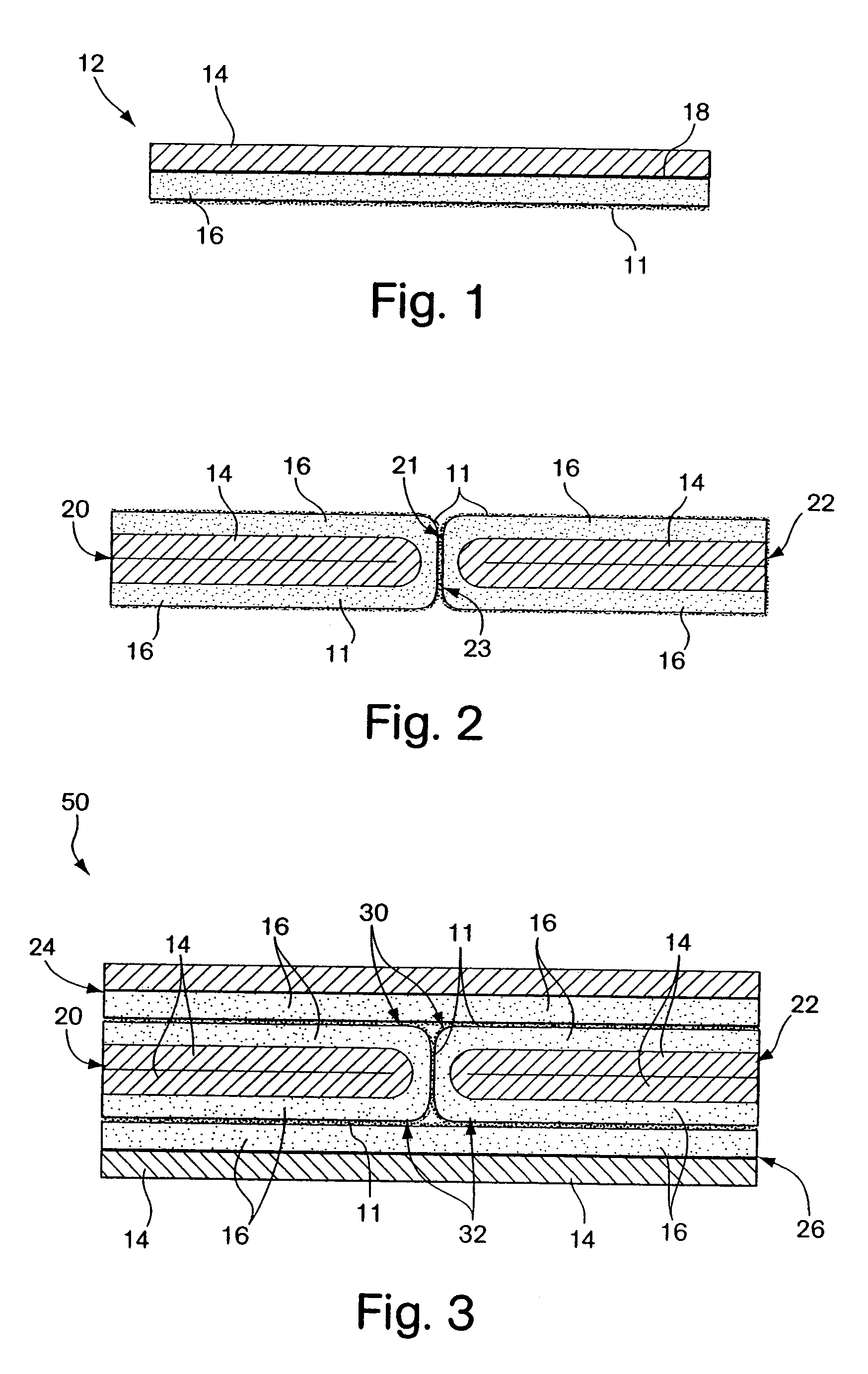
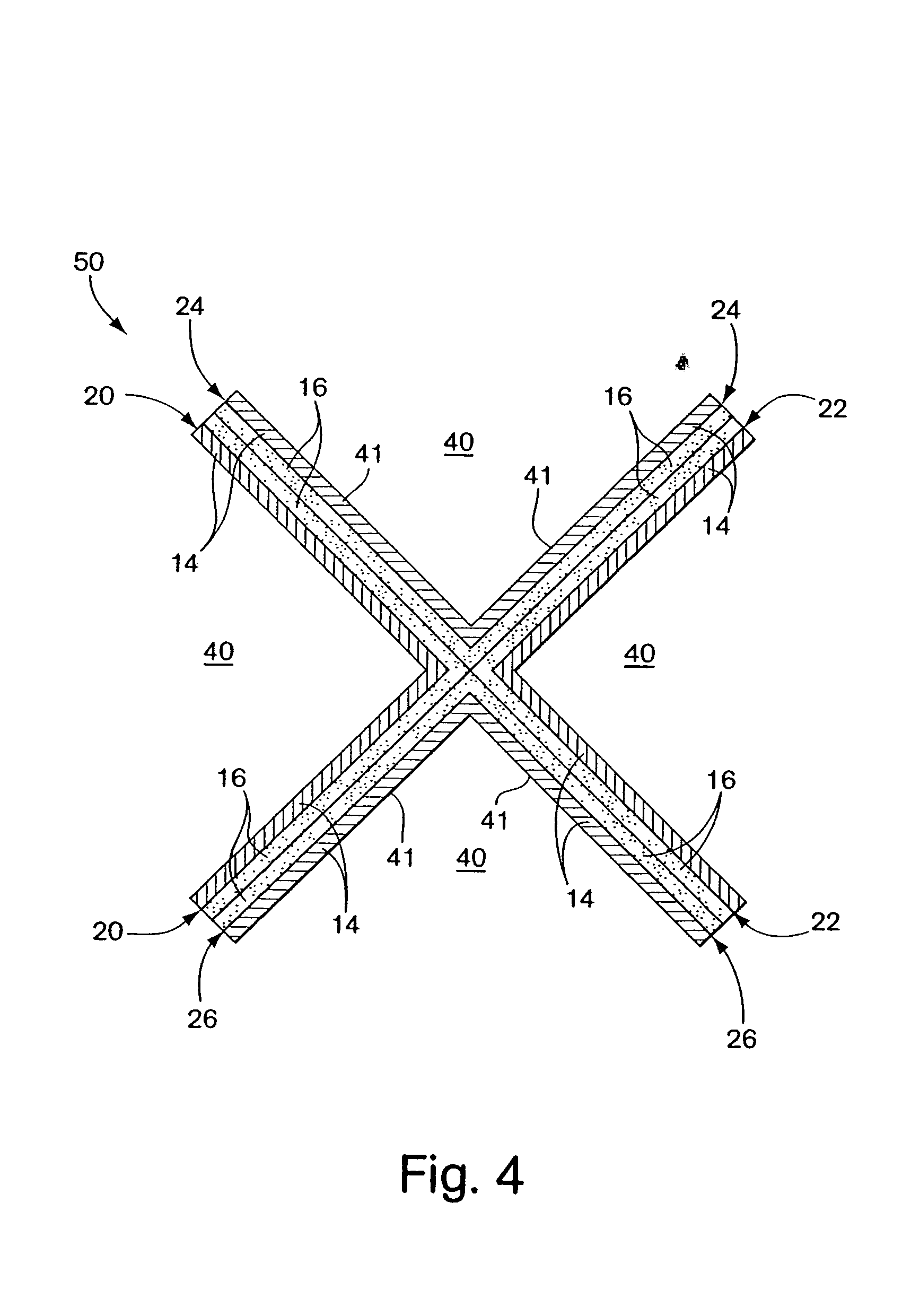
[0041]FIGS. 2–5 illustrate cross sectional views of the multifolded composite tape according to the invention. As shown in FIGS. 4–5, the multifolded composite tape comprises a single tape configuration 50 having an X-shaped cross-section or profile. The single tape configuration 50 comprises four foil / film laminates 12, wherein each foil / film laminate is constructed as described above. The four foil / film laminates are assembled to form fin-like shielding members 41 that extend radially from a center axis or a vertical center line to define four channels or grooves 40 and the X-shaped cross section. The channels or grooves 40 extend longitudinally along a length of the single tape. The foil / film laminates are assembled into the single tape configuration 50 in such a manner that the foil layers 14 are oriented on the exterior surfaces of the single tape configuration to face or define each channel or groove 40.
[0042]As shown in FIG. 2, the single X tape configuration 50 is achieved b...
second embodiment
[0048]Referring to FIGS. 6–8, cross-sectional views of the multifolded composite tape according to the invention are depicted. In this embodiment, the composite tape 60 comprises a single laminate 60 having a width sufficient to fold lengthwise into a multiple of pleats and a length substantially greater than the width to form a strip of continuous material to assemble a single tape configuration.
[0049]The single laminate 60 is similarly constructed as the laminate described with reference to FIG. 1. As shown, in FIG. 6, the single laminate 60 comprises at least one layer of a first material, such as a conductive material 14, having a length substantially longer than a width to form a strip of suitable dimensions to construct a single continuous tape. In one embodiment, the conductive material includes, although is not limited to, a metallic foil comprised of a conductive metal suitable for use in data transmission cables such as, for example, aluminum, copper, tinned copper, silver...
fifth embodiment
[0068]Referring to FIG. 13, the invention provides a communications cable 300 comprising a multifolded composite shielding tape 330 to separate and shield a multiple of conductors 320. The communications cable 300 comprises a jacket 310, a multifolded composite shielding tape 330 situated within and longitudinally coextensive with the jacket 310, and a multiple of conductors 320 disposed between fin-like shielding members 330a, 330b, 330c and 330d of the composite tape 330. As shown in FIG. 13, in one embodiment of the invention, the cable 330 includes four twisted pairs of insulated conductors 320a, 320b, 320c and 320d and the composite tape 300 defines an initial X-shaped cross-section or profile. The four fin-like shielding members 330a, 330b, 330c and 330d extend radially from a center axis or a vertical center line of the composite tape 330 and terminate proximate to the jacket 310. The four shielding members 330a, 330b, 330c and 330d define four channels or grooves 340a, 340b,...
PUM
Abstract
The invention provides a composite wrapping and shielding tape for use in cable manufacture. Embodiments of the composite tape comprise a single tape configuration to separate and shield individual pairs of insulated conductors housed within a cable such as a high-speed data communications cable. The single tape configurations of the invention are multifolded and assembled from foil / film laminates to form a plurality of longitudinal channels or grooves to accommodate one or more pairs of insulated conductors and a variety of cable designs. During cable manufacture, one or more pairs of insulated conductors is wrapped within a continuous shield provided by each longitudinal channel or groove, thereby separating and shielding each pair of insulated conductors and, hence, isolating or at least substantially reducing crosstalk between pairs of insulated conductors contained within the cable. The invention also provides methods for making a multifolded composite tape. The invention further provides a communications cable comprising a multifolded composite tape to separate and shield insulated conductors.
Description
PRIOR PENDING APPLICATIONS[0001]This application is a continuation application pursuant to 37 C.F.R. § 1.53(b) of application Ser. No. 10 / 020,582, filed Dec. 14, 2001, now U.S. Pat. No. 6,624,359 which is incorporated herein by reference.FIELD OF THE INVENTION[0002]The invention is generally directed to a composite tape for use in cable manufacture. In particular, the invention provides a multifolded composite tape constructed in a single tape configuration with a multiple of longitudinal channels or grooves for wrapping and shielding individual insulated conductors. The invention also provides methods of making a multifolded composite tape as a single tape configuration. The invention further provides a communications cable comprising a multifolded composite tape for separating and shielding one or more conductors.BACKGROUND OF THE INVENTION[0003]High-speed data communications cables currently in use include pairs of insulated conductors twisted together to form a two-conductor gro...
Claims
Application Information
Patent Timeline
Application Date:The date an application was filed.
Publication Date:The date a patent or application was officially published.
First Publication Date:The earliest publication date of a patent with the same application number.
Issue Date:Publication date of the patent grant document.
PCT Entry Date:The Entry date of PCT National Phase.
Estimated Expiry Date:The statutory expiry date of a patent right according to the Patent Law, and it is the longest term of protection that the patent right can achieve without the termination of the patent right due to other reasons(Term extension factor has been taken into account ).
Invalid Date:Actual expiry date is based on effective date or publication date of legal transaction data of invalid patent.
IPC IPC(8): H01B11/04H01B11/08
CPCH01B11/06H01B11/085
InventorBAHLMANN, CRAIGBRAUN, DAVIDFRANKLIN, ETHAN E.SIEKIERKA, TOMSHOWS, PHILIPGAREIS, GALENHEMMELGARN, GARYLINDSTRAND, DOUGLAS

