
Rotating electrical machine for vehicle

a technology of rotating electrical machines and vehicles, applied in the direction of electric generator control, dynamo-electric converter control, multiple dynamo-motor starters, etc., to achieve the effect of improving the power generation characteristic, preventing the occurrence of overvoltage, and improving the acceleration performance and fuel mileage of the vehicl

Active Publication Date: 2005-12-13
MITSUBISHI ELECTRIC CORP
View PDF15 Cites 20 Cited by
  • Summary
  • Abstract
  • Description
  • Claims
  • Application Information

AI Technical Summary

Benefits of technology

The solution effectively prevents overvoltage, improves acceleration performance, and enhances fuel mileage by allowing for the installation of permanent magnets with greater magnetizing forces, thereby improving the power generation characteristics of the alternator.

Problems solved by technology

According to the vehicular alternator referred to above, however, there arises the following problem.

Method used


Image

  • Rotating electrical machine for vehicle
  • Rotating electrical machine for vehicle
  • Rotating electrical machine for vehicle

Examples


embodiment 1

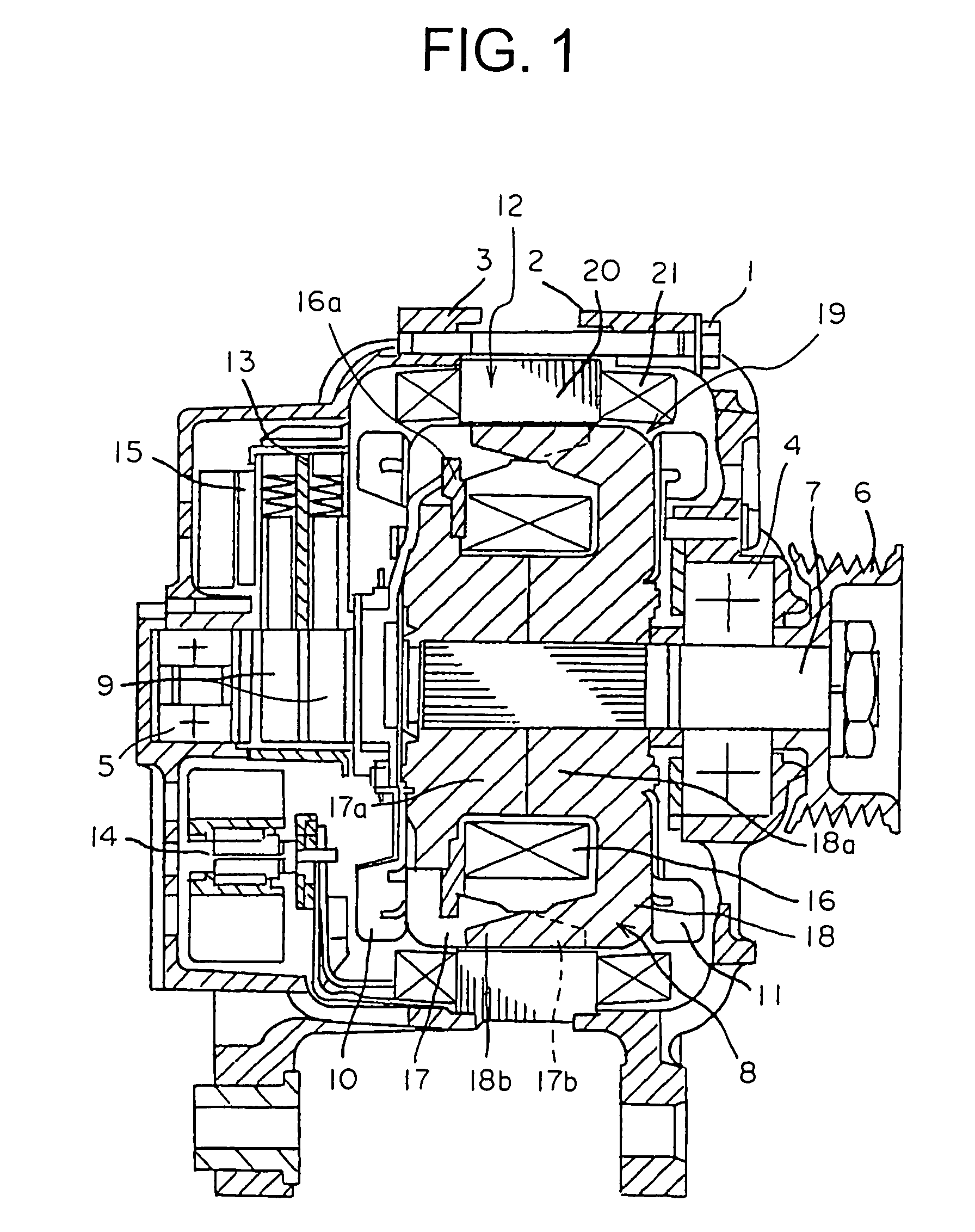
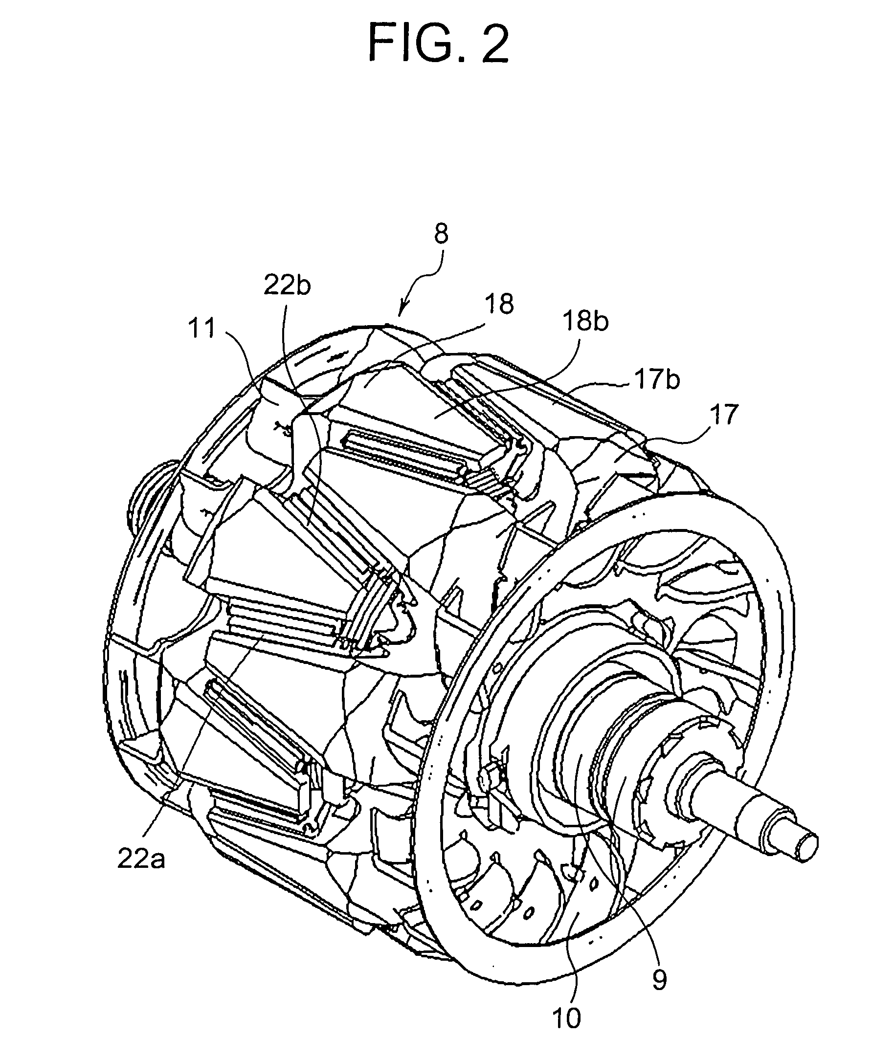
[0021]A first embodiment of the present invention will be described below based on the accompanying drawings. FIG. 1 is a cross sectional view that shows the construction of a charging generator according to a first embodiment of the present invention, and FIG. 2 is a perspective view that shows the detailed structure of a rotor of FIG. 1.

[0022]As shown in FIG. 1, this charging generator, which is an example of a rotating electrical machine, includes a casing composed of a pair of brackets 2, 3 made into an integral unit by means of bolts 1 (though only one being illustrated), a rotation shaft 7 supported by the casing through a pair of bearings 4, 5 and having a pulley 6 fixedly attached to one end thereof, a rotor 8 of a claw pole type fixedly mounted on the rotation shaft 7, slip rings 9 fixedly secured to the other end of the rotation shaft 7 for supplying current to the rotor 8, a pair of air cooling fans 10, 11 fixedly attached to the opposite side surfaces of the rotor 8, an ...

embodiment 2

[0065]A generator motor according to a second embodiment of the present invention is used by switching between the case when it functions as an electric motor for engine starting and for assist driving, and the case when it functions as a charging generator.

[0066]Here, note that symbols in FIGS. 8 and 9 to be described below in this second embodiment are the same as those in FIGS. 1 through 3 in the first embodiment, and have similar functions.

[0067]FIG. 8 is a cross sectional view that shows the construction of the generator motor according to the second embodiment of the present invention. In FIG. 8, the generator motor, which is an example of a rotating electrical machine, is further provided, as particular constructional elements in comparison with the charging generator of the first embodiment, with a rotational position detector 30 that detects the rotational position of the rotor 8, and a three-phase terminal 31 connected to armature winding 21.

[0068]FIG. 9 is a circuit diagr...


PUM


Abstract

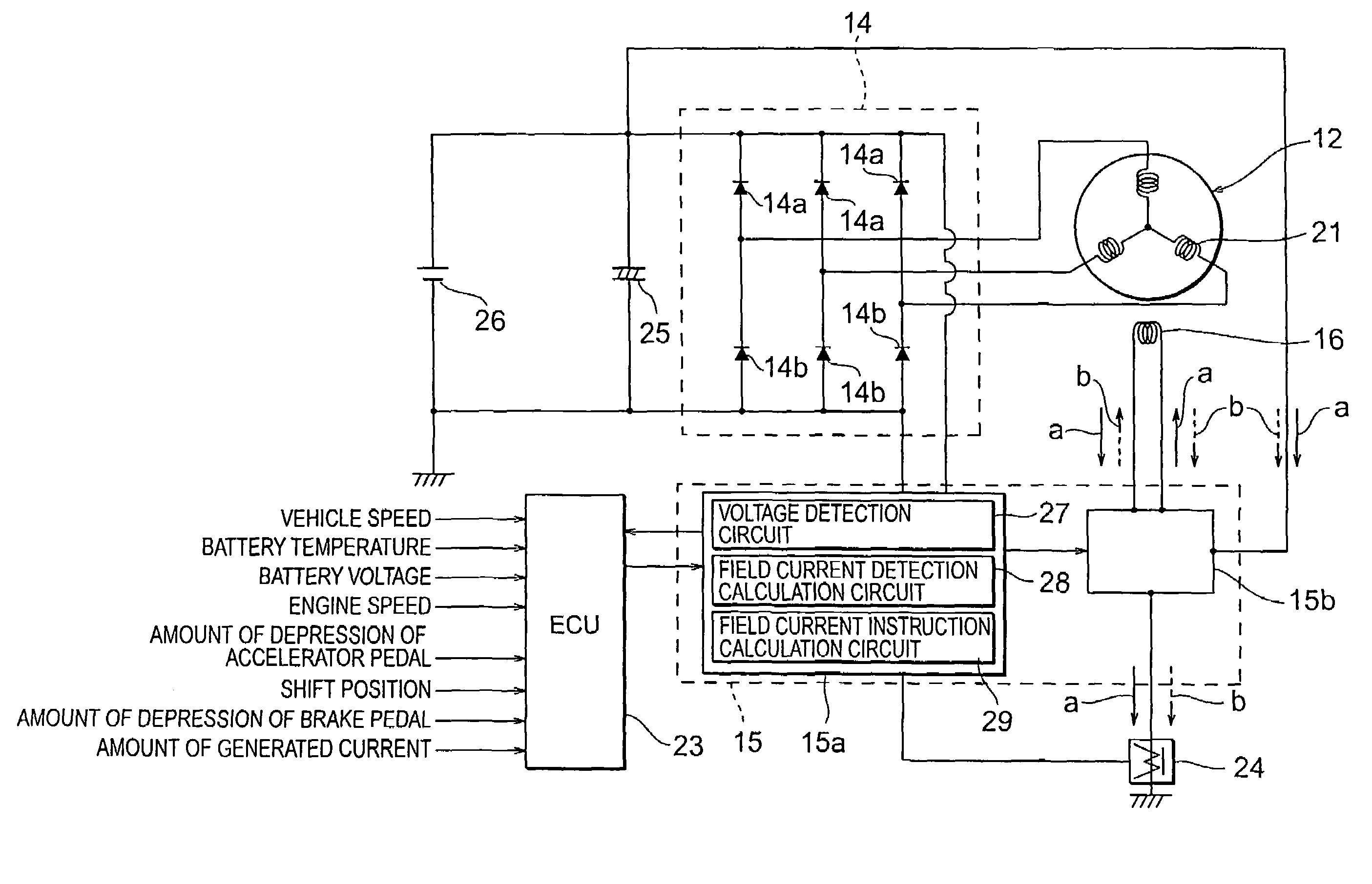
A rotating electrical machine for a vehicle is capable of improving the acceleration performance and the fuel mileage of the vehicle while achieving the prevention of occurrence of overvoltage and the improvement of its power generation characteristic at the same time. The machine includes an armature having an armature core and an armature winding wound around the armature core for generating an output voltage to charge a battery; a rotor having a rotor core with a field winding wound therearound, and permanent magnets for supplying magnetic flux to the armature core; and a voltage control section that adjust the output voltage of the armature by controlling the field current based on the value of an output voltage of the armature winding and the value and the direction of flow of the field current flowing through the field winding.

Description

BACKGROUND OF THE INVENTION[0001]1. Field of the Invention[0002]The present invention relates to a rotating electrical machine for a vehicle having a rotor with a permanent magnet for supplying magnetic flux to an armature core.[0003]2. Description of the Related Art[0004]In known vehicular alternators using a permanent magnet as a field magnet, there has been a technique that is capable of reducing the amount of electric power generation during the high speed rotation of an alternator so as to prevent the destruction thereof due to overvoltage to a battery or an electrical load. In such a technique, a permanent magnet magnetized in a direction to reduce leakage flux is interposed between the magnetic poles of a claw pole rotor, and the specification of this permanent magnet is adjusted in such a manner that the output of the alternator at a maximum rotational speed thereof when the field current of a field winding is made zero becomes a magnetic excitation force that is substantial...

Claims


Application Information

Patent Timeline
Patent Type & Authority Patents(United States)
IPC IPC(8): H02J7/16H02K19/22H02P9/14H02K21/14H02P9/04
CPCH02J7/16H02P9/02H02P9/107H02P9/48Y02T10/7005Y02T10/7022Y02T10/70
Inventor KITAMURA, YUTAKAASAO, YOSHIHITO
Owner MITSUBISHI ELECTRIC CORP
Learn More