Apparatus and system for camera head determination in an image sensing system

a technology of image sensing and camera head, applied in the direction of signal generator with optical-mechanical scanning, picture reproducers using projection devices, television systems, etc., to achieve the effect of ensuring the operation of the image sensing system

Inactive Publication Date: 2005-12-13
CANON KK
View PDF29 Cites 25 Cited by
  • Summary
  • Abstract
  • Description
  • Claims
  • Application Information

AI Technical Summary

Benefits of technology

[0044]According to the above image processing apparatus, without interchanging camera heads, it is possible to switch to the desired camera head to be used as well as the image processing apparatus can process obtained signals from the camera head. Therefore, the operability of an image sensing system, when image sensing operation is performed by using a plurality of camera heads, improves.

Problems solved by technology

However, there is an image sensing system which does not have an exclusive data line for notifying information on an image sensing device.
However, there is a limitation that the CCD used in each interchangeable camera head must have the same number of pixels and must be operated at the same video rate.
Further, in the image sensing system using an exclusive data line, when a user want to performs image sensing operation by using different camera heads, the use has to detach a currently connected camera head from the image processing unit then attach another camera, which is troublesome.

Method used


Image

  • Apparatus and system for camera head determination in an image sensing system
  • Apparatus and system for camera head determination in an image sensing system
  • Apparatus and system for camera head determination in an image sensing system

Examples


first embodiment

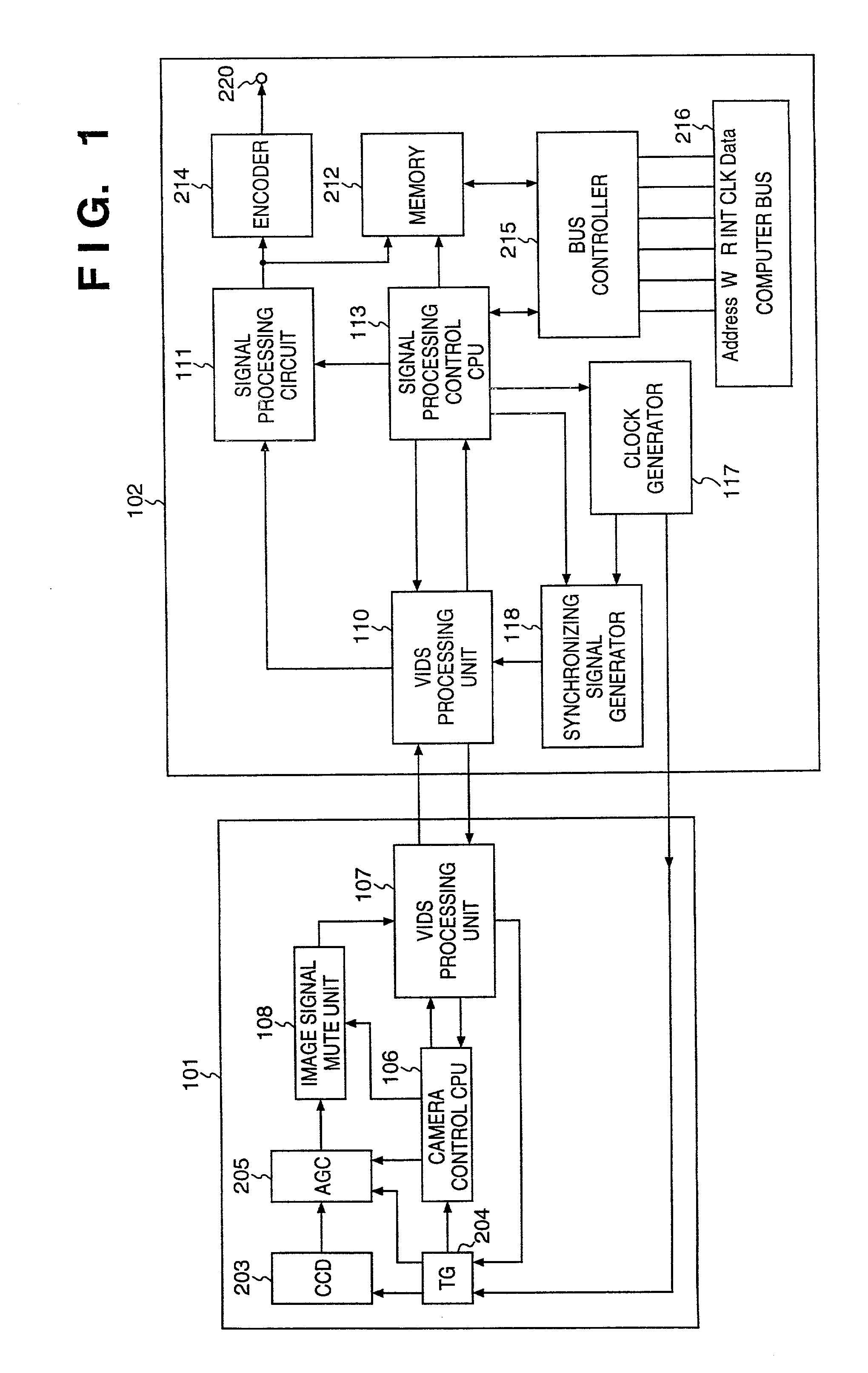
[0078]Note, in the first embodiment, both the camera head 101 and the image processing unit 102 are operated in a mode conforming to the NTSC video rate during the initial communication process, however, the present invention is not limited to this. For example, it is possible to operate the camera head 101 and the image processing unit 102 in a mode based on other video standard, such as PAL.

[0079]

[0080]FIG. 4 is a block diagram illustrating a configuration of an image sensing system according to a second embodiment of the present invention, and FIG. 5 is a flowchart showing an initial communication process in a camera head according to the second embodiment. Further, FIG. 6 is a flowchart showing an initial communication process in an image processing unit according to the second embodiment. The second embodiment will be explained with reference to FIGS. 4 to 6 below. It should be noted that the same units and elements in FIG. 4 as those in FIG. 1 of the first embodiment and in FI...

third embodiment

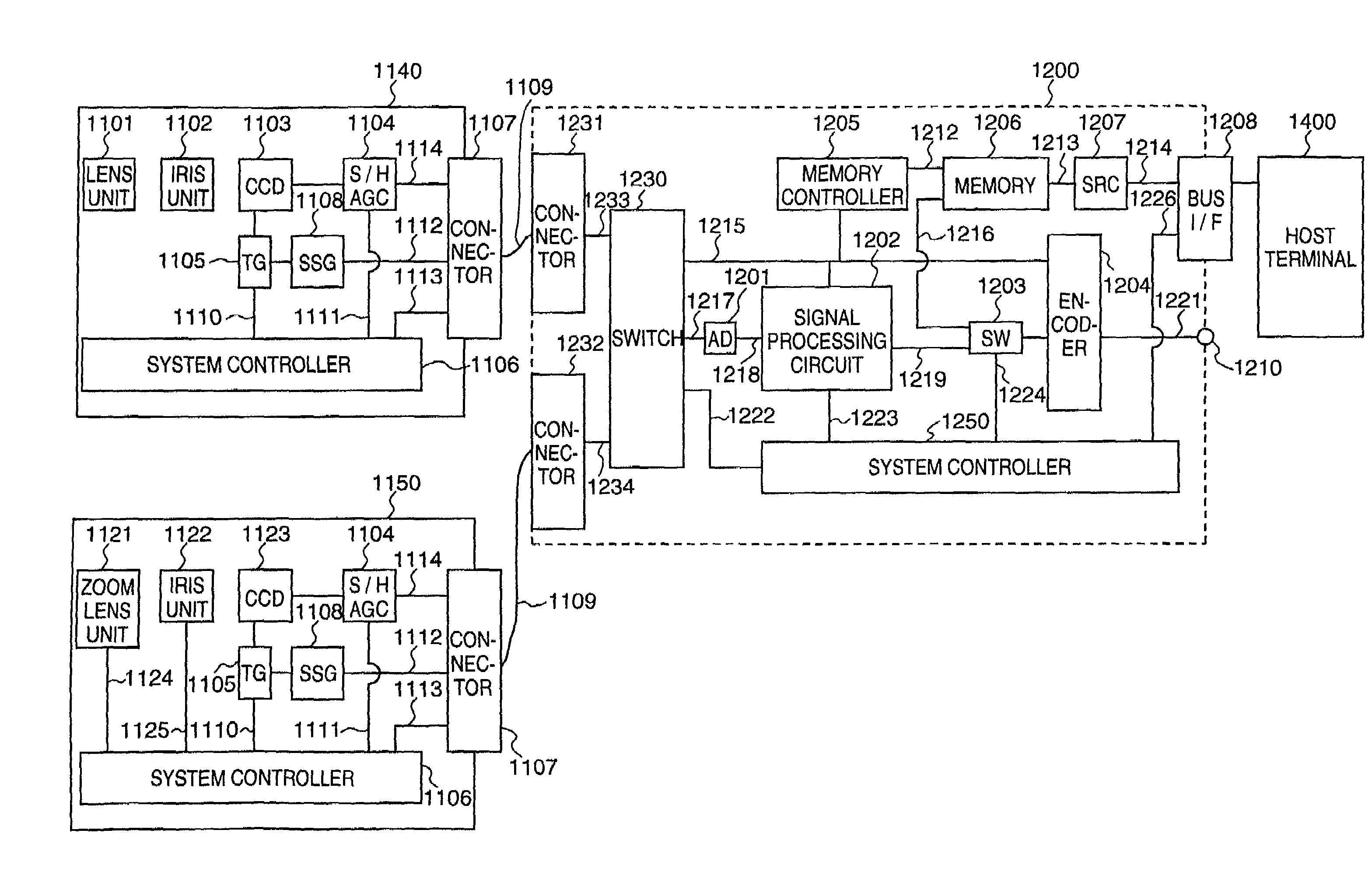
[0090]In an image sensing system whose camera head and an image processing unit can be separated in the third embodiment, a plurality of camera heads are connected to a plurality of ports of the image processing unit. The image processing unit has changeover means for switching the plurality of ports, and attributes of the camera heads connected to the plurality of ports are stored in memory means, and control means controls to perform image processes corresponding to one of the attributes of a camera head selected by switching the ports, and image signals are outputted.

[0091]FIG. 7 is a block diagram illustrating a configuration of an image sensing system according to the third embodiment of the present invention. In FIG. 7, the same units and elements as those in FIG. 17 of the conventional system are referred by the same reference numerals, and explanations of those are omitted. The units which are different from the conventional system are explained below.

[0092]Reference numeral...


PUM


Abstract

In a head detachable camera comprising a camera head and an image processing unit which does not have an exclusive line for notifying the type of image sensing device used in the camera head, when the power switch is turned on, vertical interval data signal processing units of the camera head and the image processing unit are set to a predetermined communication mode, such as one conforming to the NTSC video mode. Under this situation, identification information showing the number of pixels and the video rate used in the image sensing device is transmitted from the camera head by multiplexing the identification information in a blanking period of an image signal, and the communication mode of the camera head is changed in accordance with the number of pixels and the video rate of the image sensing device, if necessary. In the image processing unit, the communication mode is set to one corresponding to the received identification information, and the image processing unit transmits a clock and synchronizing signals corresponding to the communication mode to the camera head.

Description

[0001]This application is a continuation of U.S. Ser. No. 08 / 842,394, filed Apr. 23, 1997, now abandoned.BACKGROUND OF THE INVENTION[0002]The present invention relates to an image sensing apparatus, an image processing apparatus, and an image sensing system and, more particularly, to an image sensing apparatus suitable as a camera head of a head-detachable camera which comprises a charge-coupled device and its controller, an image processing apparatus suitable as a signal processing apparatus of the head-detachable camera for performing various signal processes on signals obtained by the camera head and generating image signals, and an image sensing system, as the head-detachable camera, comprising the above image sensing apparatus and image processing apparatus which can be separated.[0003]Conventionally, there is a head-detachable camera comprising a camera head having a charge-coupled device (CCD) and a controller for the CCD and a signal processing unit, which can be separated f...

Claims


Application Information

Patent Timeline
Patent Type & Authority Patents(United States)
IPC IPC(8): H04N5/232H04N7/088
CPCH04N5/23203H04N5/23209H04N5/772H04N5/907H04N7/083H04N7/088H04N23/66H04N23/663
Inventor IKEDA, KEIICHIHABA, YOSITO
Owner CANON KK
Why Eureka
Try Eureka