Method and apparatus for transformation of a gaussian laser beam to a far field diffraction pattern

Inactive Publication Date: 2005-12-13
KANZLER KURT
View PDF18 Cites 36 Cited by
  • Summary
  • Abstract
  • Description
  • Claims
  • Application Information

AI Technical Summary

Benefits of technology

[0019]In general terms, an apparatus according to the present invention comprises a Gaussian laser with a TEM00 fundamental mode; an off-axis blazed diffractive phase grating that shapes the Gaussian beam to a non-Gaussian intensity shape at some small diffracted angle for a single diffraction order, wherei

Problems solved by technology

However, without intensity profile shaping as a degree of freedom for design engineers, many applications cannot be realized with sufficient quality.
Furthermore, the high cost of early beam shaping techniques limited their practical use.
A limited amount of work has been performed related to using beam shapers with conventional focusing schemes.
While this Airy pattern at the focus may pr

Method used


Image

  • Method and apparatus for transformation of a gaussian laser beam to a far field diffraction pattern
  • Method and apparatus for transformation of a gaussian laser beam to a far field diffraction pattern
  • Method and apparatus for transformation of a gaussian laser beam to a far field diffraction pattern

Examples


example 1

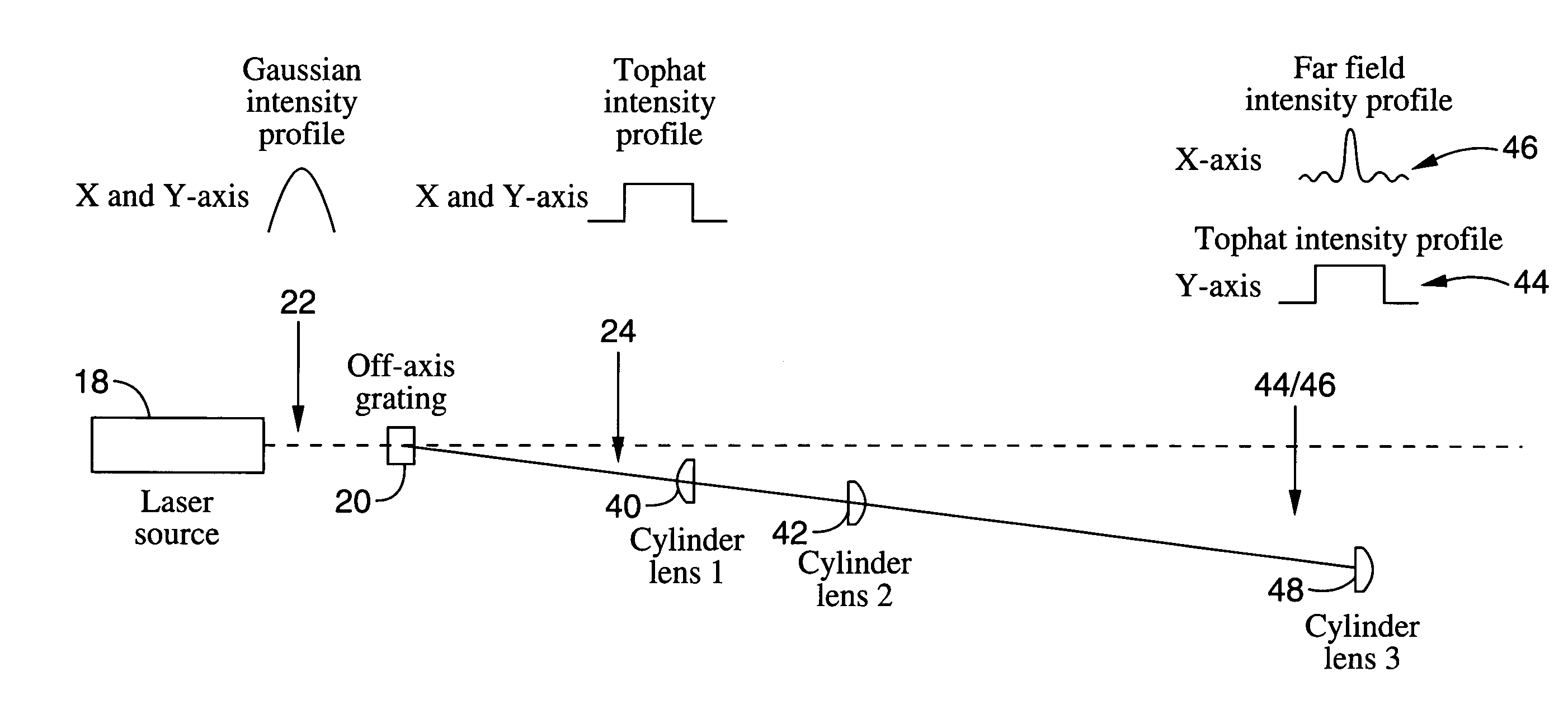
[0036]A Gaussian intensity profile He—Ne laser (632.8 nm) with a beam diameter of 0.8 mm (1 / e2) was positioned adjacent an off-axis near field beam shaper (remapping) single element diffractive optic. A pair of refractive lenses spaced at a distance to produce a slightly converging wave front were positioned downstream of the diffractive optic as shown in FIG. 3. The remapping diffractive optic was designed to produce a 10th order super-Gaussian profile at a beam diameter of 2 mm. This profile was transformed to a far field pattern by the pair of lenses. The configuration produced an intermediate focus between lens 22 and lens 24. Once the system was aligned, the far field pattern was able to propagate for several meters. With this configuration a slightly diverging far field pattern was produced and propagated through a 200 mm focal length lens. The intensity pattern around the focal plane was measured with a CCD camera and digital beam analysis software. The CCD camera had a pixel...

example 2

[0037]Consider a propagating far field pattern with a beam diameter of 3 mm (measured to the second null) where its full angle divergence is approximately 3 mrad and its wavelength is 632.8 nm. The calculated M2 is approx 11. Using a 200 mm focal length lens, the expected spot diameter is 0.3 mm. The Rayleigh range for the spot around the focal plane would be 110 mm. Since ZR only tells us about spot size, we need to bring in more information to describe the intensity profile changes around the focal plane. An example in Gori's work referenced previously (Gori, F. “Flattened Gaussian beams,” Opt. Comm. 107, pp. 335–341, 1994) describes a 632.8 nm beam with a Wo=1 mm. The ZR for this beam would be approximately 5 meters; however, Gori shows that the beam profile changes significantly over distances on the order of several hundred millimeters. For his N=25 example, the intensity profile degrades to ±15% uniformity over the flat top in a distance of 400 mm. As a rough estimate for corr...

example 3

[0038]Data was taken using both round and square uniform intensity remapping diffractive optics. For both cases, the parameters in the above example are an accurate description. The measured spot diameter at the focal plane was 0.310 mm. This value agrees with the prediction to within 5%. The measured uniform depth of field symmetric around the focal plane was 6 mm. This is a factor of 3 off the prediction, but gives us a rough order of magnitude. One possibility for this difference is that the super-Gaussian in this experiment did not equate well with the example from Gori. If the super-Gaussian used here has a steeper edge slope than Gori's example, the uniformity would degrade more rapidly and this would shorten the uniform depth of field value. Further investigation is needed to conclusively determine this difference. For the case of the square uniform profile, the values were very similar to the round case. The transform pattern for the square uniform profile takes the shape of...


PUM


Abstract

A method and apparatus for converting a Gaussian laser beam into a propagating far field diffraction pattern using an off-axis diffractive optic. This propagating far field pattern is focused by a lens to obtain a flattop intensity at the focal plane. The technique is based on the idea of Fourier transform pairs and produces a small spot diameter with a useable depth of field. A focused uniform intensity profile can be useful for many laser applications.

Description

CROSS-REFERENCE TO RELATED APPLICATIONS[0001]This application claims priority from U.S. provisional application Ser. No. 60 / 305,472 filed on Jul. 13, 2001, incorporated herein by reference.STATEMENT REGARDING FEDERALLY SPONSORED RESEARCH OR DEVELOPMENT[0002]Not ApplicableREFERENCE TO A COMPUTER PROGRAM APPENDIX[0003]Not ApplicableBACKGROUND OF THE INVENTION[0004]1. Field of the Invention[0005]The present invention pertains generally to transforming a Gaussian laser beam to a far field diffraction pattern, and more particularly to employing an off-axis blazed diffractive phase grating to shape a Gaussian beam to a non-Gaussian intensity shape at some small diffracted angle for a single diffraction order and transforming the intensity shape to its far field pattern in one or two dimensions.[0006]2. Description of the Background Art[0007]Since the time that the laser was invented and employed in labs around the world, scientists have been proposing and experimenting with various beam s...

Claims


Application Information

Patent Timeline
IPC IPC(8): G02B5/18G02B27/09H01S3/08
CPCG02B27/0927G02B27/0944
Inventor KANZLER, KURT
Owner KANZLER KURT
Why Eureka
Try Eureka