
Dehumidifier/air-conditioning system

Inactive Publication Date: 2005-12-20
DUCOOL
View PDF63 Cites 97 Cited by
  • Summary
  • Abstract
  • Description
  • Claims
  • Application Information

AI Technical Summary

Benefits of technology

[0022]Thus, in some embodiments of the invention, the amount of waste heat generated by the air-conditioner is relatively high and the heat requirements of the dehumidifier are relatively low, since a major portion of the heat for regeneration is supplied by the heat pump.
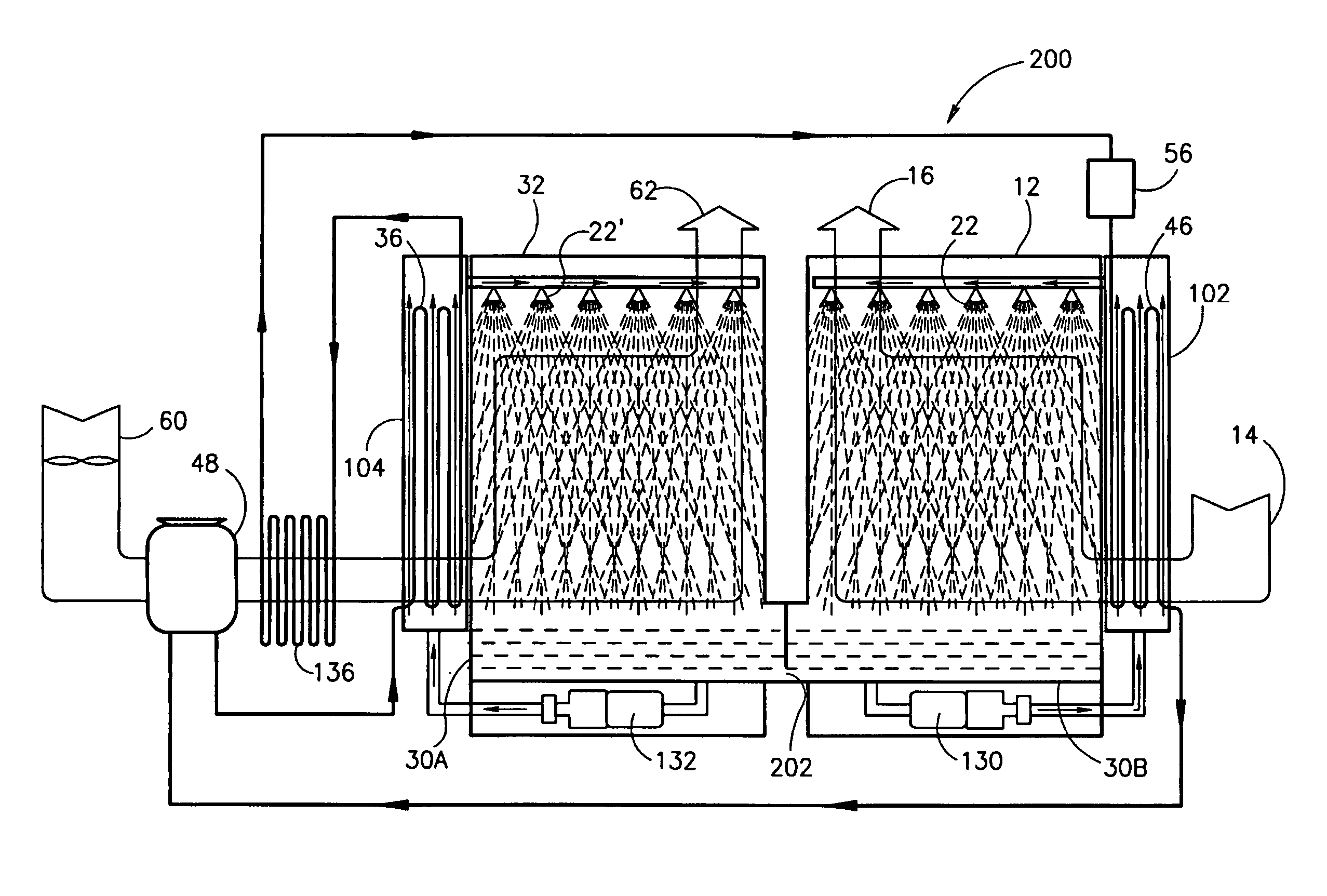
[0023]According to an aspect of some embodiments of the invention, a simple method of integration of an air conditioner and dehumidifier is provided. In accordance with an exemplary embodiment of the invention, the air conditioner and dehumidifier are separate units without conduits for air connecting the units. However, unlike prior art unintegrated units, these embodiments provide advantages of utilizing waste heat from the air conditioner to provide regeneration energy for the dehumidifier.

Problems solved by technology

The present inventors have found that in the absence of some additional cooling of refrigerant, the system reaches a steady state at a high refrigerant temperature, at which the system is inefficient.
Not only does this result in a waste of water, it also results in a lowering of the efficiency of the system.
Under most conditions, this construction will result in cooled dehumidified air being generated.

Method used


Image

  • Dehumidifier/air-conditioning system
  • Dehumidifier/air-conditioning system
  • Dehumidifier/air-conditioning system

Examples


Embodiment Construction

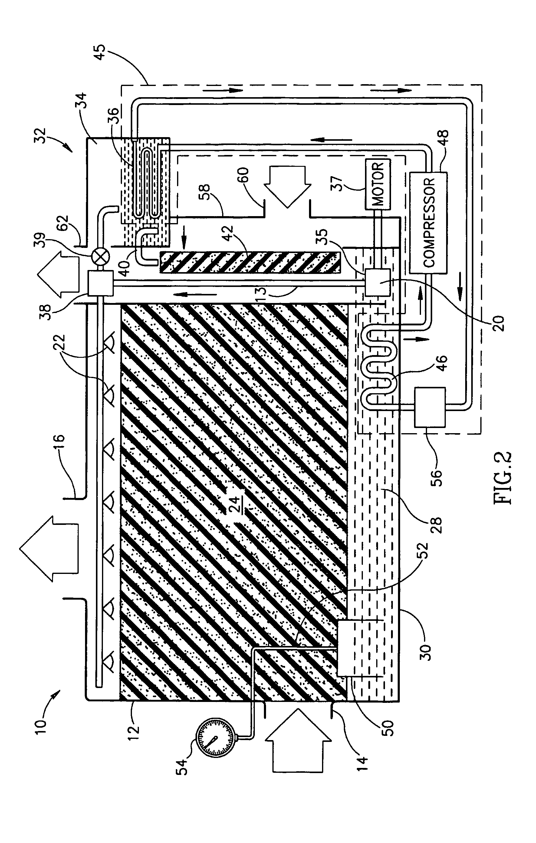
[0071]In some embodiments of the invention, the dehumidifiers described in applicants' PCT Applications PCT / IL97 / 00372, filed Nov. 16, 1997 and PCT / IL98 / 00552, filed 11 Nov. 1998, are used. The disclosures of these applications are incorporated herein by reference. These applications were published on May 27, 1999 as WO 99 / 26025 and WO 99 / 26026 respectively and subsequently filed as U.S. patent applications Ser. Nos. 09 / 554,398 and 09 / 554,397 respectively. In view of the potential utility of these dehumidifiers in the present invention, the dehumidifiers described therein are described in detail herein, together with embodiments of the present invention.

[0072]Referring first to FIG. 2, a dehumidifying system 10, as described in the above referenced applications, comprises, as its two main sections a dehumidifying chamber 12 and a regenerator unit 32. Moist air enters dehumidifying chamber 12 via a moist air inlet 14 and dried air exits chamber 12 via a dry air outlet 16.

[0073]In the...


PUM


Abstract

Apparatus for conditioning air comprising: a quantity of liquid desiccant (28); a dehumidifier section (12) in which air to be conditioned is brought into contact with a first portion of the liquid desiccant; a regenerator section (32) in which outside air is brought into contact with a second portion of the liquid desiccant; and a refrigeration system (45) having a first heat exchanger (46) associated with the first portion of liquid desiccant and a second heat exchanger (36) associated with the second portion of liquid desiccant and a third heat exchanger (136) that does not contact the liquid desiccant.

Description

RELATED APPLICATIONS[0001]This application is a U.S. national filing of PCT Application No. PCT / IL01 / 00373, filed Apr. 23, 2001. This application is also a continuation in part of U.S. patent application Ser. No. 09 / 554,397 filed May 15, 2000, now U.S. Pat. No. 6,487,872 which is a US National Phase of PCT / IL98 / 00552 filed 11 Nov. 1998 and a continuation in part of U.S. application Ser. No. 09 / 936,671 filed Sep. 14, 2001, now U.S. Pat. No. 6,494,053 which is a 371 of PCT / IL00 / 00105, filed Feb. 20, 2000, the disclosures of all of which are incorporated herein by reference.FIELD OF THE INVENTION[0002]The present invention is related to the field of environmental control systems and more particularly, to the field of systems which combine dehumidification and air conditioning.BACKGROUND OF THE INVENTION[0003]In general, air conditioning systems not only reduce the temperature of the ambient air, but also remove substantial amounts of water from it. This is especially true when the air ...

Claims


Application Information

Patent Timeline
IPC IPC(8): F24F3/153B01D53/26F24FF24F3/14F24F5/00F25D17/00F25D17/06F25D23/00
CPCF24F3/1417F24F5/001F24F2003/144
Inventor FORKOSH, MORDECHAIFORKOSH, DANFORKOSH, TOMY
Owner DUCOOL
Learn More