
Two-stroke engine having a membrane valve integrated into the transfer channel

a technology of membrane valve and transfer channel, which is applied in the direction of valve arrangement, combustion engine, cylinder, etc., can solve the problems of unnecessary sealing measures, and achieve the effect of avoiding additional sealing surfaces and reliable assembly of membrane valves

Inactive Publication Date: 2005-12-20
ANDREAS STIHL AG & CO KG
View PDF13 Cites 5 Cited by
  • Summary
  • Abstract
  • Description
  • Claims
  • Application Information

AI Technical Summary

Benefits of technology

[0004]It is an object of the invention to provide a two-stroke engine which is so improved that a reliable assembly of a membrane valve is provided while avoiding additional seal surfaces.
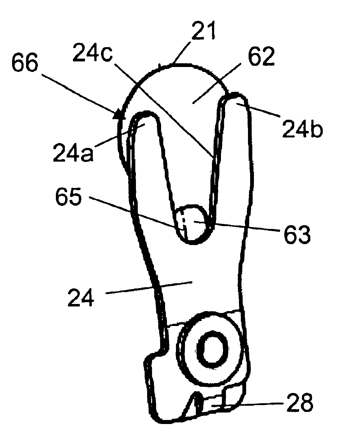
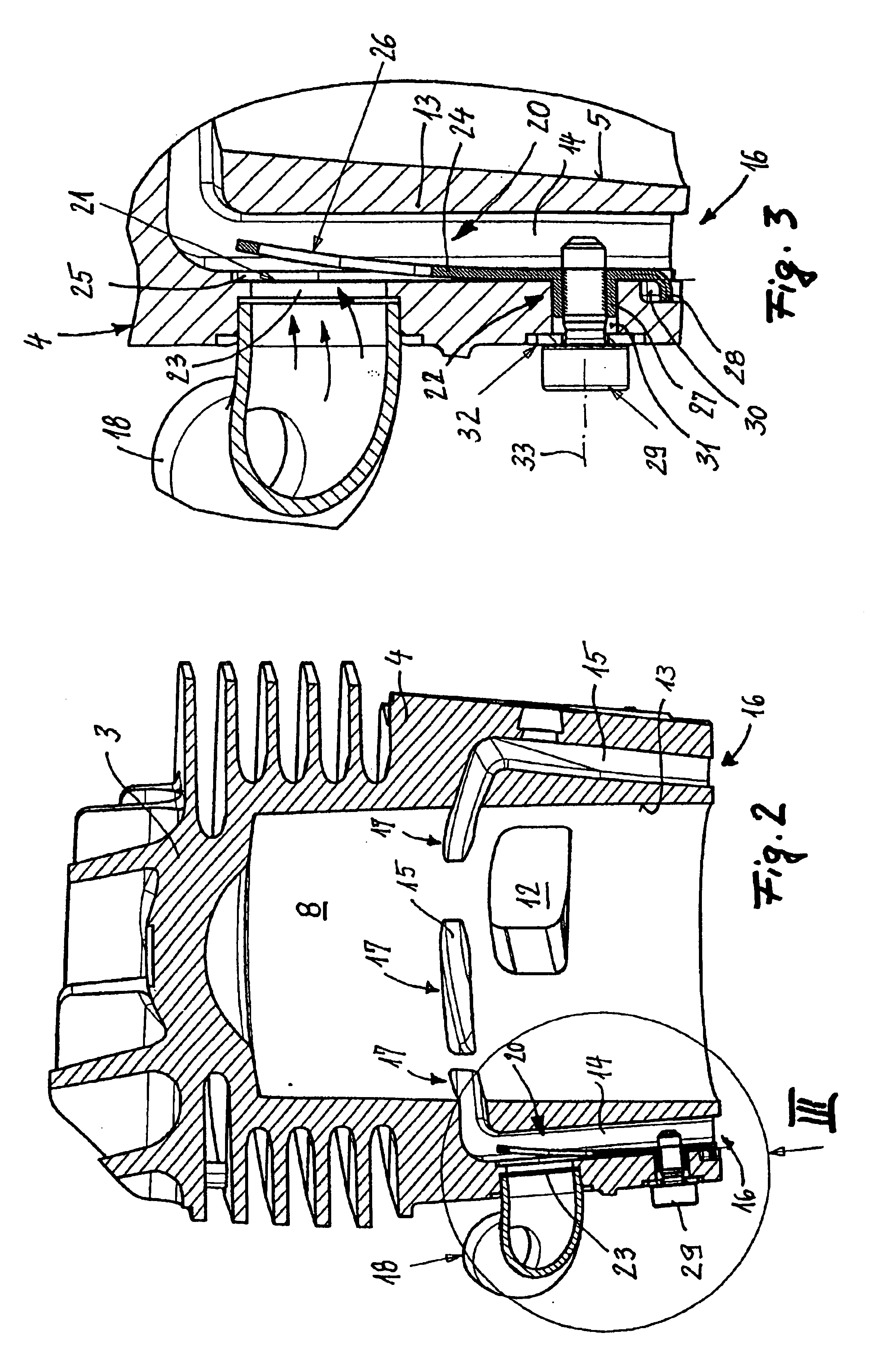
[0010]In order to ensure a precisely functioning reliable assembly of the membrane valve even by an inexperienced assembler or without sight control, projections are provided on the membrane carrier which engage in assigned openings of the cylinder wall. A first projection can be configured as a stop against rotation and a second projection can be configured as an assembly aid. The attachment screw advantageously engages in the projection forming the assembly aid. For this purpose, the projection, which defines the assembly aid, is configured as a cylinder bushing which lies with an approximate fit in a through bore for the attachment screw. The attachment screw is then screwed into the assembly projection of the membrane carrier and supports itself with its head against an outer annular shoulder of the cylinder wall. In this way, large attachment forces can be developed which ensure a reliable fixing of the membrane valve in the transfer channel.

Problems solved by technology

The otherwise necessary additional sealing measures are unnecessary because of this arrangement of the membrane valve.

Method used


Image

  • Two-stroke engine having a membrane valve integrated into the transfer channel
  • Two-stroke engine having a membrane valve integrated into the transfer channel
  • Two-stroke engine having a membrane valve integrated into the transfer channel

Examples


Embodiment Construction

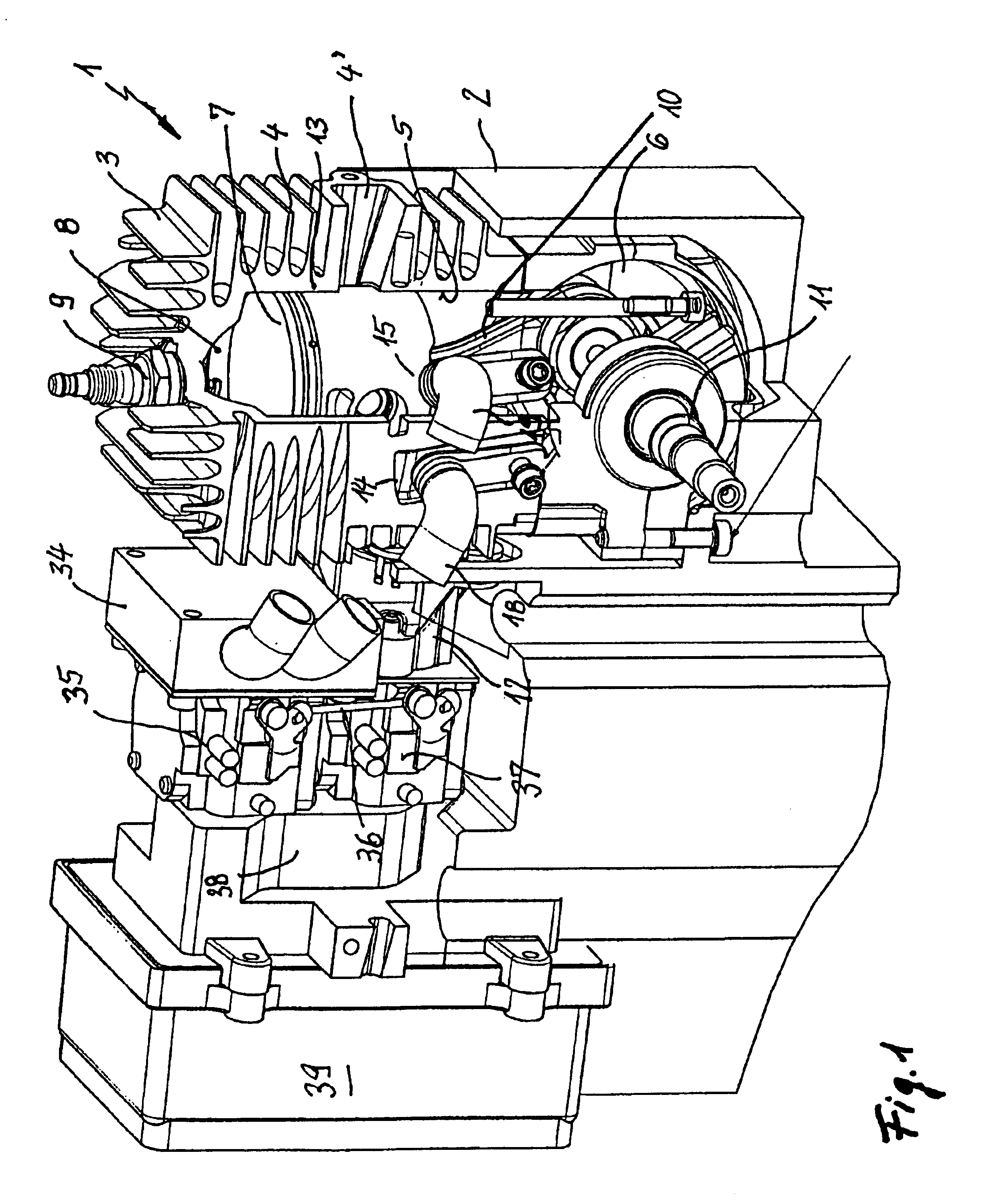
[0027]FIG. 1 shows an internal combustion engine 1 in a housing 2 of a portable handheld work apparatus. The work apparatus can be a lawnmower, a motor-driven chain saw, a cutoff machine, a blower apparatus, a brushcutter or the like.

[0028]The internal combustion engine 1 comprises a cylinder 4 which is configured as one piece with the cylinder head 3 in the embodiment shown. The cylinder bore 5 is open toward the crankcase 6 and a reciprocating piston 7 is displaceably arranged in the cylinder bore 5. The piston 7, the cylinder 4 and the cylinder head 3 all conjointly delimit a combustion chamber 8 to which a spark plug 9 is assigned.

[0029]The piston 7 drives a crankshaft 11 via a connecting rod 10. The crankshaft 11 drives a work tool and is rotatably supported in the crankcase 6.

[0030]The crankcase 6 is connected to a mixture inlet 12 (FIG. 2) which is formed in the cylinder wall 13 and controlled by the piston 7. As can be seen especially from FIG. 2, the combustion chamber 8 is...


PUM


Abstract

A mixture lubricated two-stroke engine includes a cylinder (4) having a cylinder head (3) and a cylinder bore (5) open to the crankcase (6). A piston (7) is displaceably arranged in the cylinder bore (5). The piston (7) and the cylinder (4) conjointly delimit a combustion chamber (8). A mixture is led into the crankcase (6) via a mixture inlet (12). The crankcase (6) is flow connected to the combustion chamber (8) via transfer channels (14, 15). The transfer channels (14, 15) are open at their ends (16) toward the crankcase (6) and are connected to bypass channels (18, 19) between the ends (16) of the transfer channels facing toward the crankcase and their ends (17) facing toward the combustion chamber. The bypass channels (18, 19) supply air and open via a membrane valve (20) into the transfer channels. The membrane (21) of the membrane valve (20) is held on a wall part of the transfer channel (14, 15). For a simple configuration, the membrane (21) is positioned in the transfer channel (14, 15) axially through the end (16) of the transfer channel (14, 15) facing toward the crankcase and is fixedly mounted on the cylinder (4) in the region of the end (16) facing toward the crankcase.

Description

RELATED APPLICATION[0001]This application is a continuation-in-part application of U.S. patent application Ser. No. 10 / 125,601, filed Apr. 19, 2002, (now U.S. Pat. No. 6,644,251), and claims priority of German patent application 101 19 282.7, filed Apr. 20, 2001.FIELD OF THE INVENTION[0002]The invention relates to a two-stroke engine including a mixture lubricated two-stroke engine for a portable handheld work apparatus, such as a motor-driven chain saw, cutoff machine, blower apparatus, brushcutter or the like.BACKGROUND OF THE INVENTION[0003]A two-stroke engine of the above kind is disclosed in U.S. Pat. No. 6,216,650. The bypass channel, which supplies clean air, opens via a membrane valve into the transfer channel which is configured as a radially open channel. The radial opening of the transfer channel is closed by a valve housing which carries the membrane valve and which is to be mounted on the cylinder. This requires a significant manufacturing and assembly effort because th...

Claims


Application Information

Patent Timeline
Patent Type & Authority Patents(United States)
IPC IPC(8): F01L3/20F02B25/22F02B33/04F02B33/30F02B63/02F02B75/02F02F1/00
CPCF01L3/205F02B25/22F02B33/04F02B33/30F02B63/02F02F1/002F02B2075/025
Inventor KLARIC, IGOR
Owner ANDREAS STIHL AG & CO KG
Learn More