
Fuel pump drive system in an internal combustion engine

a technology of internal combustion engine and drive system, which is applied in the direction of liquid fuel feeders, machines/engines, machine supports, etc., can solve the problems of increasing assembly and maintenance costs, increasing power transmission losses from crankshafts, and increasing costs

Active Publication Date: 2005-12-20
INT ENGINE INTPROP CO LLC
View PDF13 Cites 16 Cited by
  • Summary
  • Abstract
  • Description
  • Claims
  • Application Information

AI Technical Summary

Benefits of technology

The patent describes a fuel pump drive system for an internal combustion engine with a double overhead camshaft. The system includes a cam-to-cam gear in the double overhead camshaft that drives the fuel pump gear. The system may have one or more primary camshafts, secondary camshafts, and fuel pumps. The cam-to-cam gear engages the cam-to-cam gear, which causes the fuel pump gear to rotate and drive the fuel pump. The technical effect of this system is to provide a more efficient and reliable fuel pump drive for internal combustion engines.

Problems solved by technology

The idler gear is an additional part that may increase assembly and maintenance costs and may increase power transmission losses from the crankshaft.
An idler gear and / or other extension to the fuel pump gear may be used, but may increase costs and increase power transmission losses in the engine.
The drive belt is an additional part that may increase assembly and maintenance costs and may increase power transmission losses from the crankshaft.
The drive belt connection of a fuel pump pulley to the crankshaft may increase the space requirements of the engine.

Method used


Image

  • Fuel pump drive system in an internal combustion engine
  • Fuel pump drive system in an internal combustion engine
  • Fuel pump drive system in an internal combustion engine

Examples


Embodiment Construction

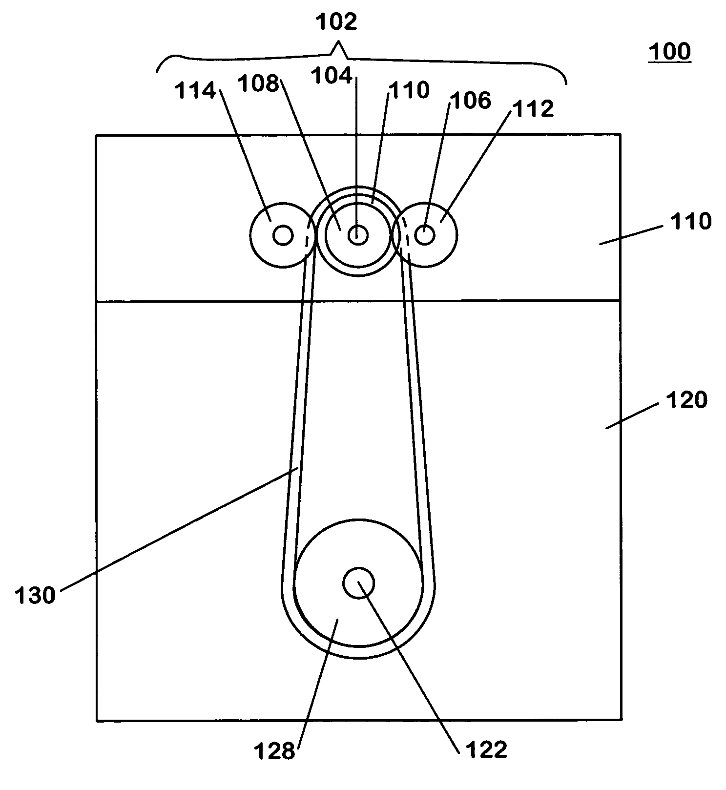
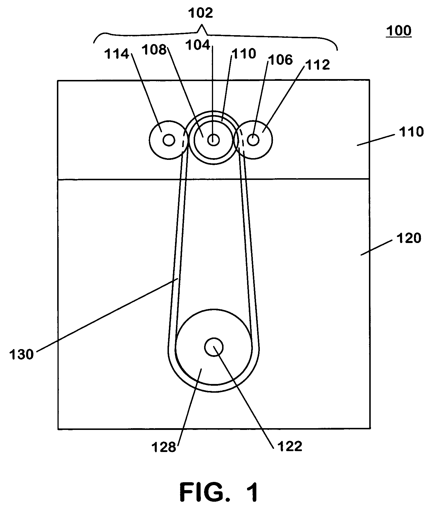
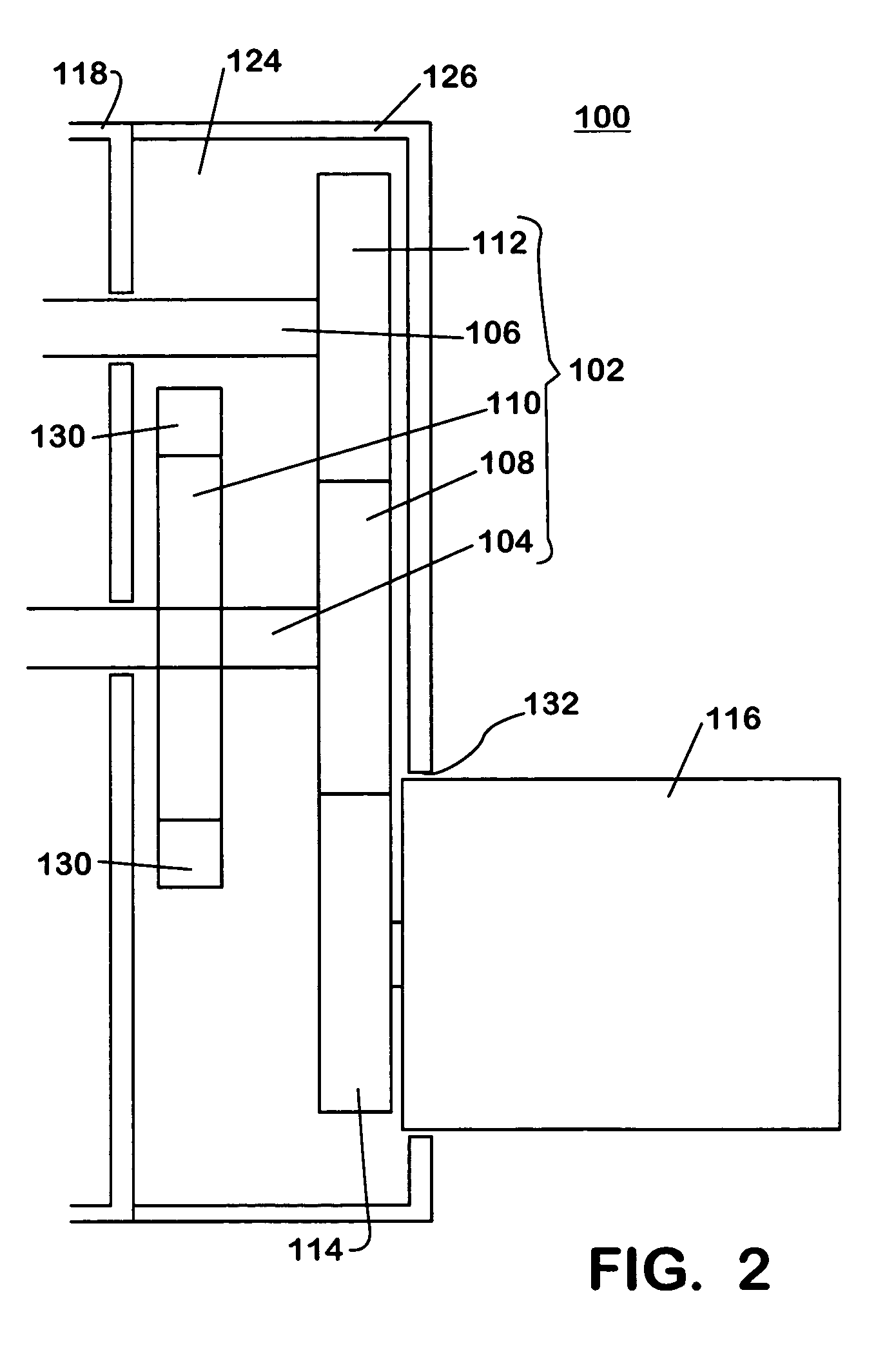
[0021]FIGS. 1 and 2 are schematic views of a fuel pump drive system in an internal combustion engine 100. A double overhead camshaft 102 is disposed in the internal combustion engine 100. The double overhead camshaft 102 includes a primary camshaft 104 and a secondary camshaft 106. The primary camshaft 104 has a cam-to-cam gear 108 and a camshaft gear 110. The cam-to-cam gear 108 engages a cam gear 112 on the secondary camshaft 106. The cam-to-cam gear 108 also engages a fuel pump gear 114 connected to a fuel pump 116. During operation of the internal combustion engine 100, the primary camshaft 104 rotates the cam-to-cam gear 108. The rotation of the cam-to-cam gear 108 turns the cam gear 112 and the fuel pump gear 114. The rotation of the cam gear 112 turns the secondary camshaft 106. The rotation of the fuel pump gear 114 drives the fuel pump 116. While a particular configuration is shown, the fuel pump drive system may have other configurations including those with additional com...


PUM


Abstract

A fuel pump drive system for an internal combustion engine uses a cam-to-cam gear from a double overhead camshaft to rotate a fuel pump gear. The fuel pump drive system may have a primary camshaft, a secondary camshaft, and the fuel pump. The primary camshaft has a camshaft gear and the cam-to-cam gear. The secondary camshaft has a cam gear. The cam gear engages the cam-to-cam gear. The fuel pump has a fuel pump gear that engages the cam-to-cam gear. The fuel pump gear drives the fuel pump.

Description

FIELD OF THE INVENTION[0001]This invention generally relates to internal combustion engines with overhead camshafts, including, but not limited to, internal combustion engines with double overhead camshafts and mechanically driven fuel pumps.BACKGROUND OF THE INVENTION[0002]Internal combustions engines convert chemical energy from a fuel into mechanical energy. The fuel may be petroleum-based (gasoline or diesel), natural gas, a combination thereof, or the like. Some internal combustion engines, such as gasoline engines, inject an air-fuel mixture into one or more cylinders for ignition by a spark from a spark plug or the like. Other internal combustion engines, such as diesel engines, compress air in the cylinder and then inject fuel into the cylinder for the compressed air to ignite. A diesel engine may use a hydraulically activated electronically controlled unit injection (HEUI) system or the like to control the fuel injection into the cylinders. The ignited fuel generates rapidl...

Claims


Application Information

Patent Timeline
Patent Type & Authority Patents(United States)
IPC IPC(8): F02M37/04F02M39/02
CPCF01L1/022F01L1/026F02M39/02F01L2001/0537F02M37/04
Inventor MANTRI, SUBHASH V.
Owner INT ENGINE INTPROP CO LLC
Learn More