Centrifugal extractor of non-contact journaled construction

a centrifugal extractor and non-contact technology, applied in centrifuges, separation processes, nuclear elements, etc., can solve the problems of rust in the rolling bearing, deterioration of a lubricating agent (grease), and inability to carry out long-term operation without maintenance, and achieve high reliability.

Inactive Publication Date: 2005-12-20
JAPAN ATOMIC ENERGY AGENCY INDEPENDANT ADMINISTRATIVE CORP
View PDF31 Cites 9 Cited by
  • Summary
  • Abstract
  • Description
  • Claims
  • Application Information

AI Technical Summary

Benefits of technology

[0009]It is an object of the present invention to provide a long service-life type centrifugal extractor in which even under the environment of corrosive gas or a mist-like liquid such as nitric acid mists generated in the reprocessing process for a spent nuclear fuel, no problem in corrosion or deterioration of parts to provide high reliability, and operation is enabled for a long period of time free from maintenance.

Problems solved by technology

However, the interior of the centrifugal extractor used in the reprocessing process for a spent nuclear fuel is exposed to the nitric acid mists generated on the process, as described above, and therefore, rust in the rolling bearing and deterioration of a lubricating agent (grease) occur, and operation for a long period of time cannot be carried out without maintenance unless the measures against the nitric acid mists such as air purge are taken.
Further, even if ceramic materials are sued in place of the stainless steel (SUS 440C), the lubricating agent unavoidably deteriorates, making it difficult to operate continuously for a long period of time.

Method used


Image

  • Centrifugal extractor of non-contact journaled construction
  • Centrifugal extractor of non-contact journaled construction

Examples


Embodiment Construction

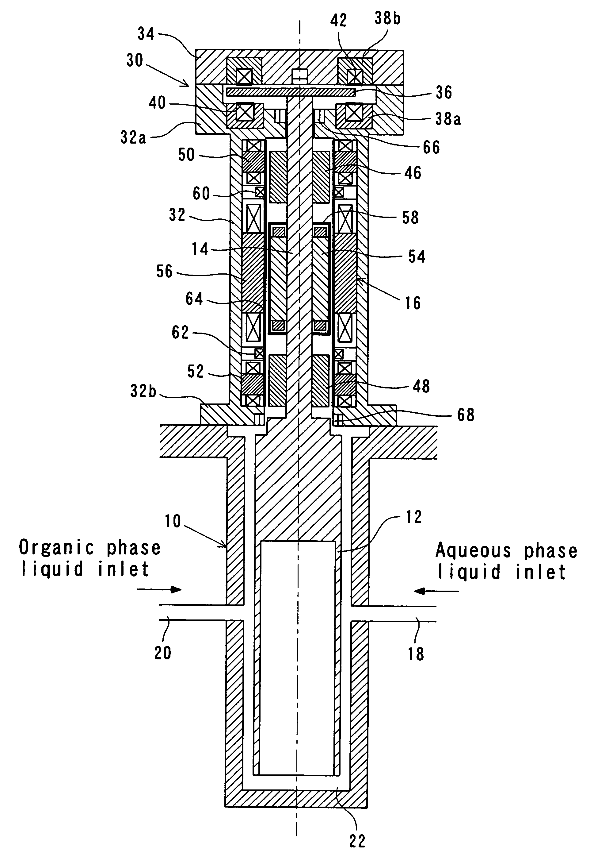
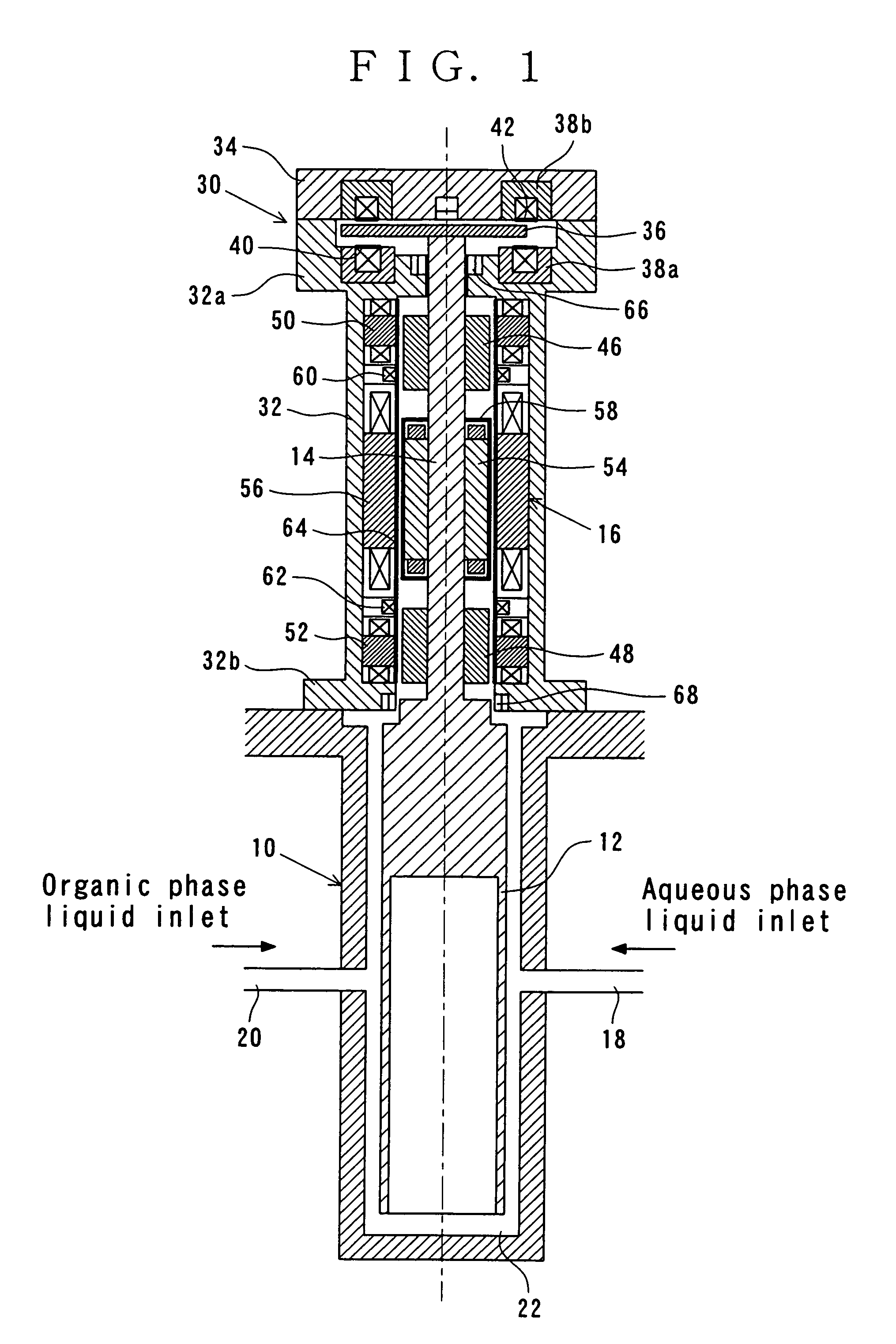
[0016]FIG. 1 is a longitudinal sectional view showing an embodiment of a centrifugal extractor of non-contact journaled construction according to the present invention. In the centrifugal extractor, a rotor 12 is housed in a lower rotor housing 10 through a gap, and the rotor 12 is rotatably journaled in a state suspended by an upwardly extending main shaft 14. The main shaft 14 is rotated and driven by a motor 16 whereby the rotor 12 is rotated. Thereby, an aqueous phase and an organic phase are supplied from liquid inlets 18 and 20, respectively, provided on the side wall of the rotor housing 10, and are mixed by rotation of the rotor 12 in a gap (mixing portion 22) between the rotor housing 10 and the rotor 12, a mixed phase being sucked into the rotor 12 from a lower-end opening of the rotor 12. Then, it is separated into two phases in a centrifugal force field internally of the rotor 12, and the separated phases are respectively fed to the succeeding stage. These rotor housing ...


PUM


Abstract

A centrifugal extractor of non-contact journaled construction is provided in which, even under the environments of corrosive gase and mist-like liquid such as nitric acid mist generated in the reprocessing of a spent nuclear fuel, no problem in corrosion or deterioration of parts occurs and high reliability is obtained, and operation is enabled for a long period of time free from maintenance. A rotor 12 housed in a rotor housing 10 is journaled by a main shaft 14 and rotated and driven by a motor 16. The main shaft is surrounded by a drive-portion housing 30, and has a thrust magnetic disk 36 on the upper end and radial magnetic disks 46, 48 and a motor-rotor portion 54 in the circumference thereof. Thrust bearing electromagnets 38a, 38b, radial bearing electromagnets 50, 52 and a motor stator portion 56 are incorporated into the drive-portion housing, and covered by non-magnetic anticorrosive protective plates 40, 42, and a protective pipe 64, the motor-rotor portion being also covered by a protective can 58. Slide bearings 66, 68 for touch down made of fluorocarbon resin are disposed on the upper end of the main shaft and on the inner wall of the drive-portion housing in the vicinity of the upper end of the rotor.

Description

BACKGROUND OF THE INVENTION[0001]The present invention relates to a centrifugal extractor of non-contact journaled construction using magnetic bearings, and in more detail, relates to a centrifugal extractor of non-contact journaled construction devised, in extracting and separating U (uranium) and Pu (plutonium) under the environment of corrosive gas and mist-like liquid in a reprocessing process of a spent nuclear fuel, so as to be able to plan the high reliance and long service life.[0002]There is a Purex (Plutonium Reduction Oxidation) process which is one of reprocessing methods for a spent nuclear fuel produced from nuclear facilities. This process is, as is well-known, a process for dissolving a spent nuclear fuel into nitric acid, and separating and recovering U and Pu dissolved in the nitric acid aqueous solution by solvent extraction operation.[0003]There are some kinds of apparatuses for carrying out the solvent extraction operation, one of which is a centrifugal extracto...

Claims


Application Information

Patent Timeline
Patent Type & Authority Patents(United States)
IPC IPC(8): B01D11/04B04B5/12G21C19/46B04B9/04B04B9/12F16C39/02
CPCB01D11/048B04B5/12B04B9/04B04B9/12F16C32/047F16C39/02
Inventor OGINO, HIDEKIFUJISAKU, KAZUHIKOWASHIYA, TADAHIRO
Owner JAPAN ATOMIC ENERGY AGENCY INDEPENDANT ADMINISTRATIVE CORP
Why Eureka
Try Eureka