
Enhanced focusing of propagating waves by compensation for medium attenuation

a propagating wave and compensation technology, applied in the field of enhanced focusing of propagating waves by compensating for medium attenuation, can solve the problems of uneven attenuation situations, undesirable deviations in amplitude, and degradation of focus, and achieve the effect of high-quality ultrasound imaging

Inactive Publication Date: 2005-12-20
BULLIS JAMES K
View PDF5 Cites 73 Cited by
  • Summary
  • Abstract
  • Description
  • Claims
  • Application Information

AI Technical Summary

Benefits of technology

[0020]An object is to provide safety in ultrasound imaging without causing undue reduction in level of transmitted signals from transducers.
[0024]An object is to establish a fairing surface that simplifies control of signal amplitudes that are transmitted from various transducer elements.

Problems solved by technology

Problems arise when attenuation is uneven for different paths such that amplitude variations occur along a wavefront.
When a coupling fluid is used to allow waves to travel between a transducer and a body it often happens that uneven attenuation situations are set up.
Undesirable deviations in amplitude can result.
This problem is especially significant for high resolution imaging which depends on large apertures and high frequency signals.
It is known that this effect also causes degradation of focus.
There is a danger with such water filled accessories because the signals at a focus point are not attenuated for shallow operation as they are naturally for deep operation.
This method couples the maximum power to the focal point but may not satisfactorily control sidelobe response for a variety of phantom shapes.
Like water stand-offs in clinical practice, this method couples the maximum amount of power intensity to the focal point but it may not necessarily produce the desired control of sidelobe response.

Method used


Image

  • Enhanced focusing of propagating waves by compensation for medium attenuation
  • Enhanced focusing of propagating waves by compensation for medium attenuation
  • Enhanced focusing of propagating waves by compensation for medium attenuation

Examples


Embodiment Construction

[0038]The scope of the invention should be determined by the appended claims and their legal equivalents and not by the examples and variations given. Actual medical practice would be expected to result in many variations of this concept.

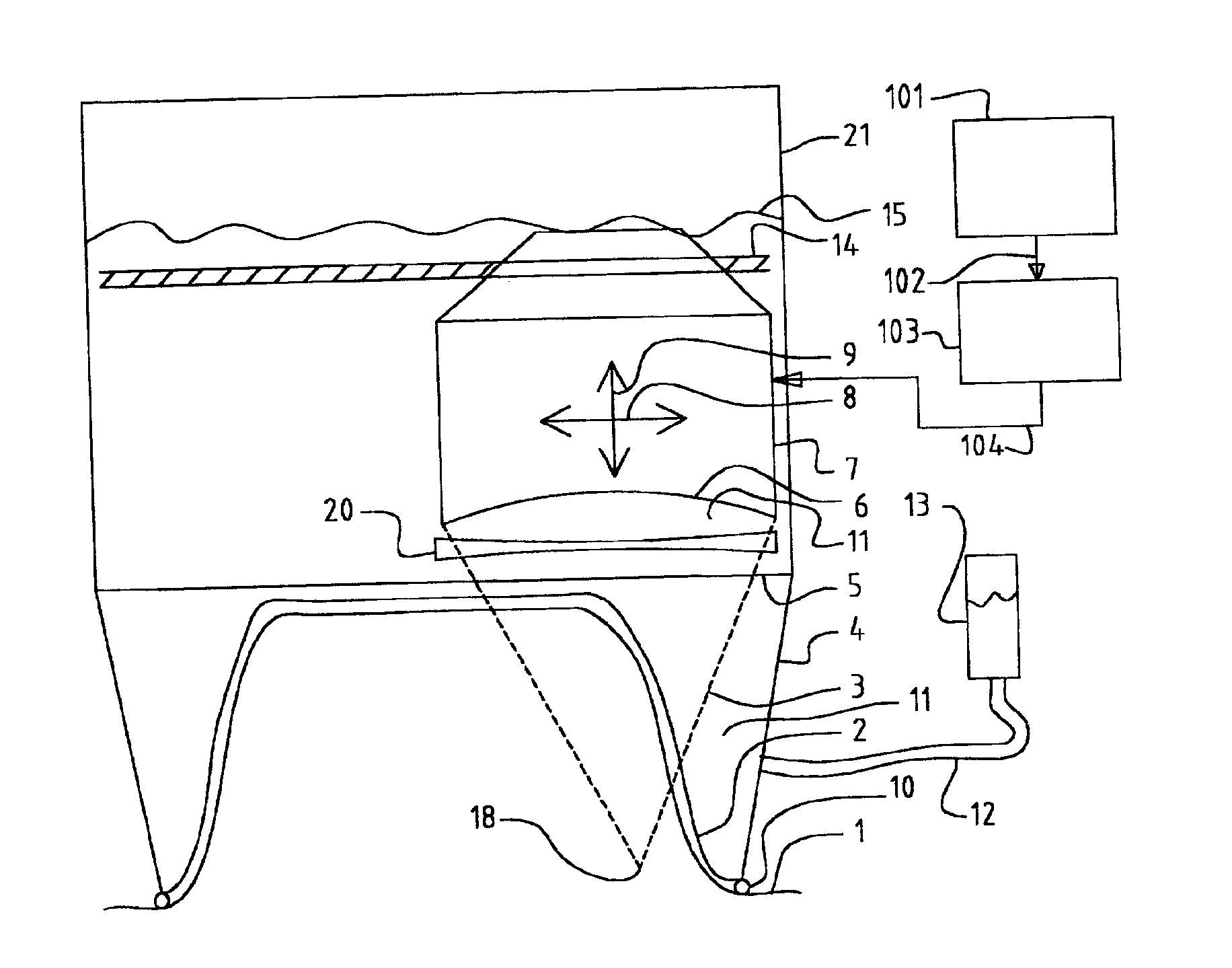
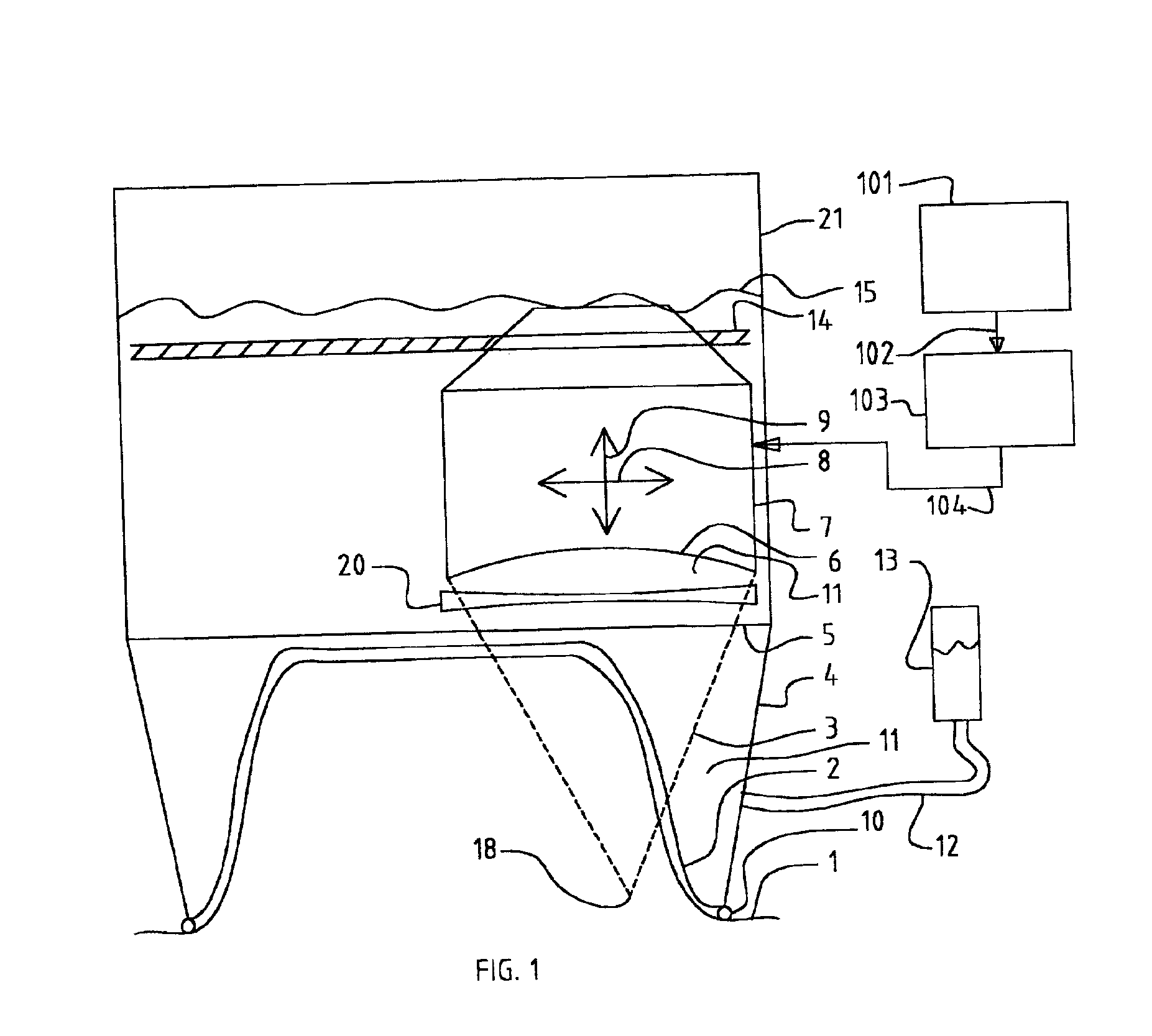
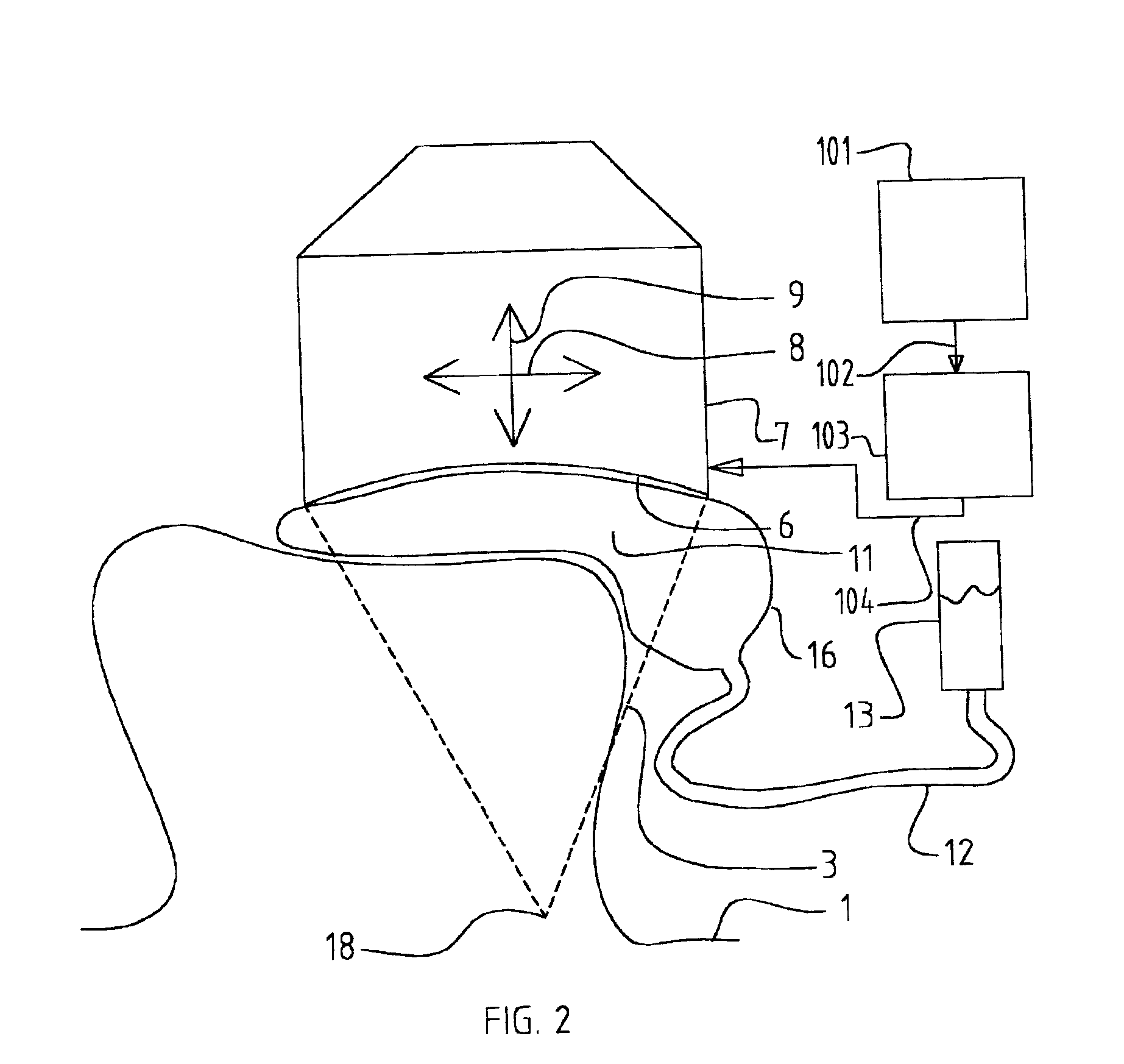
[0039]This invention involves an interface that can be described as a drum where one end of the drum has a thin rubber sheet fastened to one end of the cylindrical shell of the drum. The other end of the drum has a sheet of Mylar drawn tightly over the other end. The cylindrical shell of the drum is actually a tapered cylinder, that is, a hollow cone. This forms a container that is filled with attenuating fluid that attenuates at the same rate per cm per MHz. as does the body part that is to be examined. Using predictions of this rate, signals are generated that emphasize the frequency spectrum to balance the attenuation effects such that after reception, the intended level spectrum occurs. The rubber sheet conforms to the body part. The Mylar sheet...


PUM


Abstract

Improved focusing of waves is accomplished by compensation for attenuation effects in a medium. The invention is a combination of a method of attenuation leveling to allow operation over uneven surfaces and a method of signal compensation for attenuation that varies with frequency. This combination allows effective focusing of wide band wave signals that operate through irregular surfaces that cause uneven attenuation effects. Apparatus is provided to implement this method in clinical applications and research applications. Spatial attenuation leveling is accomplished with material that attenuates like the body part to be imaged. Compensation for attenuation that varies with frequency is provided by electronic modification of signal waveforms. Applications in the field of ultrasonic imaging in human tissue are specifically discussed. The apparatus includes conformal surfaces that are in contact with a patient's body that serve to prevent direct contact of the body with the attenuating material. It also includes fairing surfaces that modify shape of a patient's body to enable scanning of surfaces. Alternate devices include stand-off devices and immersion configurations.

Description

BACKGROUND OF THE INVENTION[0001]1. Field of the Invention[0002]The invention relates to creating images by transmitting signals and sensing the effect of objects in the field of view on the signals.[0003]2. Description of the Prior Art[0004]Ultrasonic, or ultrasound, imaging devices depend on signal wavefronts that propagate into the body. A wavefront can be described by connecting points of equal phase at a given point in time to form a surface that is perpendicular to the direction that ray paths propagate. The wavefront emanates from a transducer aperture and is shaped by a combination of the transducer surface shape and phasing of signals from separate elements of the transducer surface. For focused operation, the wavefront converges to a point, except that diffraction prevents perfect convergence. Successive wavefronts act like new sources of the signal that are ever smaller and closer to the focus point. The reverse process similarly applies to reception where signals from a ...

Claims


Application Information

Patent Timeline
Patent Type & Authority Patents(United States)
IPC IPC(8): A61B8/00G01S7/52G10K11/02
CPCA61B8/4281G01S7/52046G10K11/02
Inventor BULLIS, JAMES K.
Owner BULLIS JAMES K
Features
  • Generate Ideas
  • Intellectual Property
  • Life Sciences
  • Materials
  • Tech Scout
  • Unparalleled Data Quality
  • Higher Quality Content
  • 60% Fewer Hallucinations
Learn More