
Mobility assist device

a technology of assist device and mobility, which is applied in the direction of brake system, navigation instrument, instruments, etc., can solve the problems of compromising collision avoidance and lane keeping, affecting the safety of vehicles, and difficult to identify obstacles and road boundaries,

Inactive Publication Date: 2005-12-20
UNIV OF MINNESOTA
View PDF54 Cites 171 Cited by
  • Summary
  • Abstract
  • Description
  • Claims
  • Application Information

AI Technical Summary

Benefits of technology

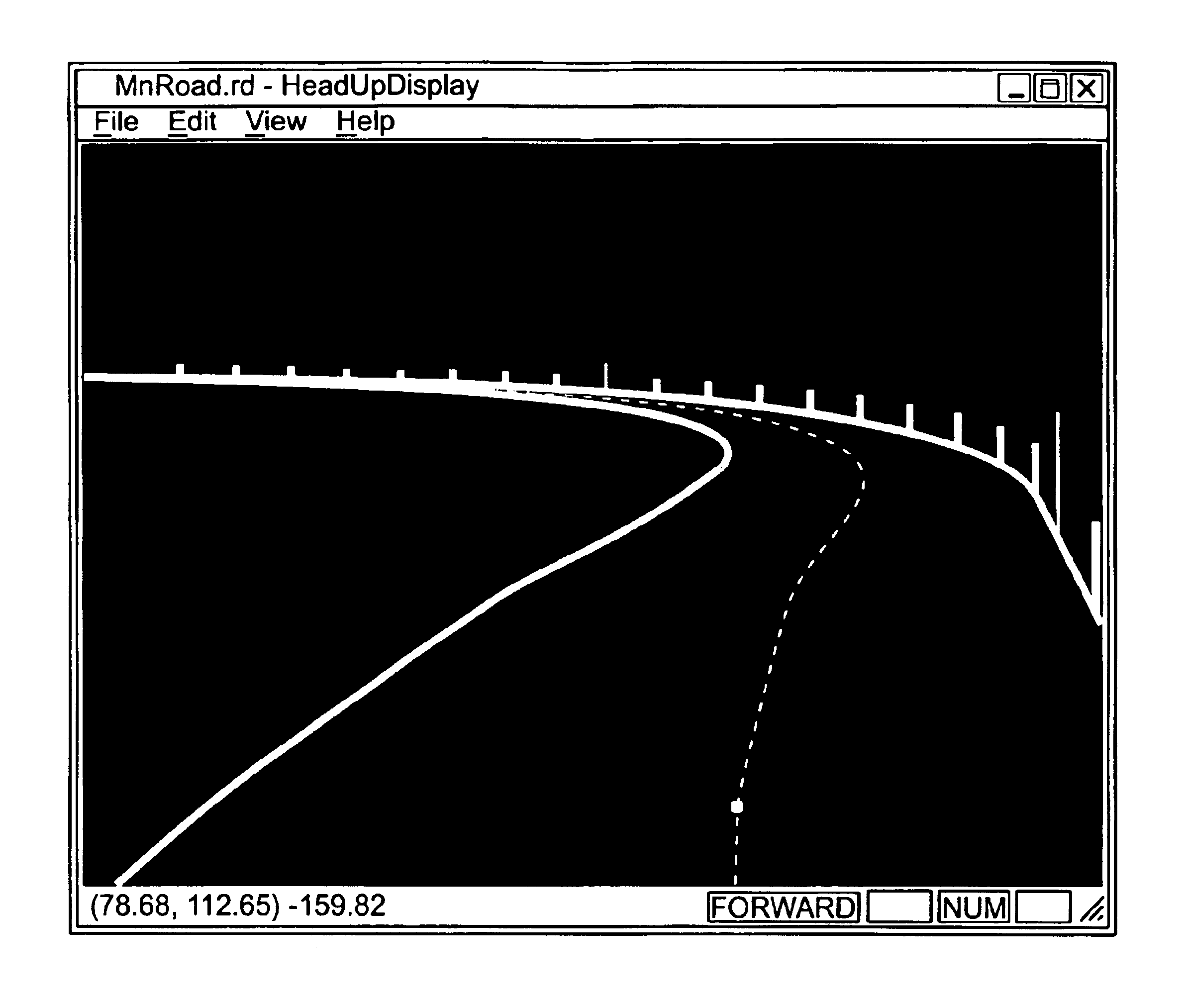
[0008]The present invention is directed to a visual assist device which provides a conformal, augmented display to assist in movement of a mobile body. In one example, the mobile body is a vehicle (motorized or non-motorized) and the present invention assists the driver in either lane keeping or collision avoidance, or both. The system can display lane boundaries, other navigational or guidance elements or a variety of other objects in proper perspective, to assist the driver. In another example, the mobile body is a person (or group of people) and the present invention assists the person in either staying on a prescribed path or collision avoidance or both. The system can display path boundaries, other navigational or guidance elements or a variety of other objects in proper perspective, to assist the walking person.

Problems solved by technology

The ability to adequately maintain both collision avoidance and lane keeping is greatly compromised when the forward-looking visual field of a driver is obstructed.
For example, heavy snowfall, heavy rain, fog, smoke, darkness, blowing dust or sand, or any other substance or mechanism which obstructs (either partially or fully) the forward-looking visual field of a driver makes it difficult to identify obstacles and road boundaries which, in turn, compromises collision avoidance and lane keeping.
Similarly, even on sunny, or otherwise clear days, blowing snow or complete coverage of the road by snow, may result in a loss of visual perception of the road.
Such “white out” conditions are often encountered by snowplows working on highways, due to the nature of their task.
The driver's forward-looking vision simply does not provide enough information to facilitate safe control of the vehicle.
This can be exacerbated, particularly on snow removal equipment, because even on a relatively calm, clear day, snow can be blown up from the front or sides of snowplow blades, substantially obstructing the visual field of the driver.
This higher brightness level causes the iris to adapt to the increased brightness and, as a result, the eye becomes insensitive to the darker objects behind the glaring snowflakes, which are often vital to driving.
Research has also been done which indicates that prolonged deprivation of visual stimulation can lead to confusion.
This can lead to control confusion which makes it difficult for the pilot to control the vehicle.
Many other environments are also plagued by poor visibility conditions.
Further, in mining environments or simply when driving on a dirt, sand or gravel surface particulate matter can obstruct vision.
In water-going vehicles, it can be difficult to navigate through canals, around rocks, into a port, or through lock and dams because obstacles may be obscured by fog, below the water, or by other weather conditions.
Similarly, surveyors may find it difficult to survey land with dense vegetation or rock formations which obstruct vision.

Method used


Image

  • Mobility assist device
  • Mobility assist device
  • Mobility assist device

Examples


Embodiment Construction

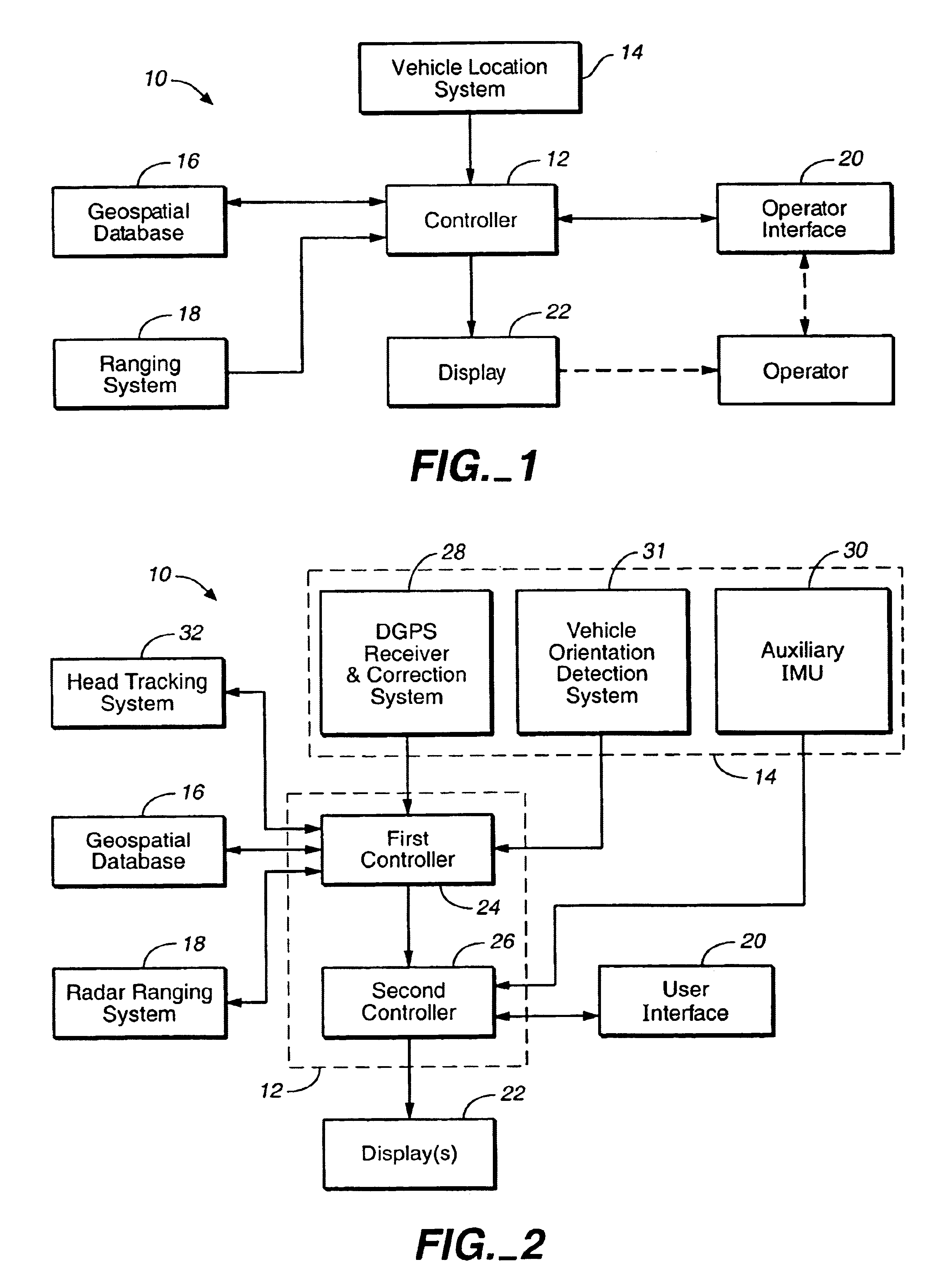
[0023]The present invention can be used with substantially any mobile body, such as a human being, a motor vehicle or a non-motorized vehicle. However, the present description proceeds with respect to an illustrative embodiment in which the invention is implemented on a motor vehicle as a driver assist device. FIG. 1 is a simplified block diagram of one embodiment of driver assist device 10 in accordance with the present invention. Driver assist device 10 includes controller 12, vehicle location system 14, geospatial database 16, ranging system 18, operator interface 20 and display 22.

[0024]In one embodiment, controller 12 is a microprocessor, microcontroller, digital computer, or other similar control device having associated memory and timing circuitry. It should be understood that the memory can be integrated with controller 12, or be located separately therefrom. The memory, of course, may include random access memory, read only memory, magnetic or optical disc drives, tape memo...


PUM


Abstract

The present invention is directed to a visual mobility assist device which provides a conformal, augmented display to assist a moving body. When the moving body is a motor vehicle, for instance (although it can be substantially any other body), the present invention assists the driver in either lane keeping or collision avoidance, or both. The system can display objects such as lane boundaries, targets, other navigational and guidance elements or objects, or a variety of other indicators, in proper perspective, to assist the driver.

Description

BACKGROUND OF THE INVENTION[0001]The present invention deals with mobility assistance. More particularly, the present invention deals with a vision assist device in the form of a head up display (HUD) for assisting mobility of a mobile body, such as a person, non-motorized vehicle or motor vehicle.[0002]Driving a motor vehicle on the road, with a modicum of safety, can be accomplished if two different aspects of driving are maintained. The first is referred to as “collision avoidance” which means maintaining motion of a vehicle without colliding with other obstacles. The second aspect in maintaining safe driving conditions is referred to as “lane keeping” which means maintaining forward motion of a vehicle without erroneously departing from a given driving lane.[0003]Drivers accomplish collision avoidance and lane keeping by continuously controlling vehicle speed, lateral position and heading direction by adjusting the acceleration and brake pedals, as well as the steering wheel. Th...

Claims


Application Information

Patent Timeline
IPC IPC(8): B60R1/00G09G5/00
CPCB60R1/00G01C21/365B60R2300/205B60R2300/301B60R2300/302B60R2300/305B60R2300/307B60R2300/60B60R2300/804B60R2300/8093B60T2201/08B60T2201/086
Inventor DONATH, MAXSHANKWITZ, CRAIG R.LIM, HEON MINNEWSTROM, BRYANGORJESTANI, ALECPARDY, SAMEERALEXANDER, LEECHENG, PI-MING
Owner UNIV OF MINNESOTA
Learn More