Camera control system

a control system and camera technology, applied in the field of cameras, can solve the problems of insufficient dealing, inability to view the situation around the subject, and inability to view the situation further, and achieve the effect of giving an instruction quickly and momentarily

Inactive Publication Date: 2005-12-20
CANON KK
View PDF10 Cites 129 Cited by
  • Summary
  • Abstract
  • Description
  • Claims
  • Application Information

AI Technical Summary

Benefits of technology

[0012]Accordingly, the present invention has been developed with a view to eliminating such a problem, and it is an object of the invention to provide an arrangement capable of easily and momentarily giving an instruction on a camera posture or the like the user desires.
[0014]A further object of the invention is to eliminate distortion occurring at a peripheral portion of the moving image and to process the moving image into a panoramic image.

Problems solved by technology

However, in the case of these conventional systems, video images transmitted are only video images of a subject actually picked up by a panhead-mounted camera at some points of time, with the result that it is impossible to view the situations around the subject and further to beforehand know, by intuition, video images to be picked up after movements of the panhead.
However, the image of the entire area produced by such image processing is a still image but not a video image to be obtained in real time.
Therefore, a problem arises in that difficulty is encountered to deal sufficiently with the cases that there is an extreme need to set the camera at a desired angle momentarily, such as the case that a camera is to be pointed at a participant asking to speak in a video conference and the case that the camera is to be pointed at a trespasser appearing suddenly in remote surveillance.

Method used


Image

  • Camera control system
  • Camera control system
  • Camera control system

Examples


first embodiment

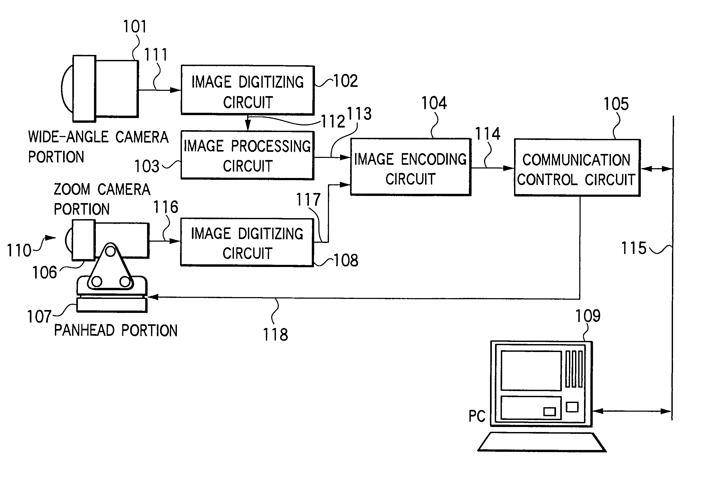
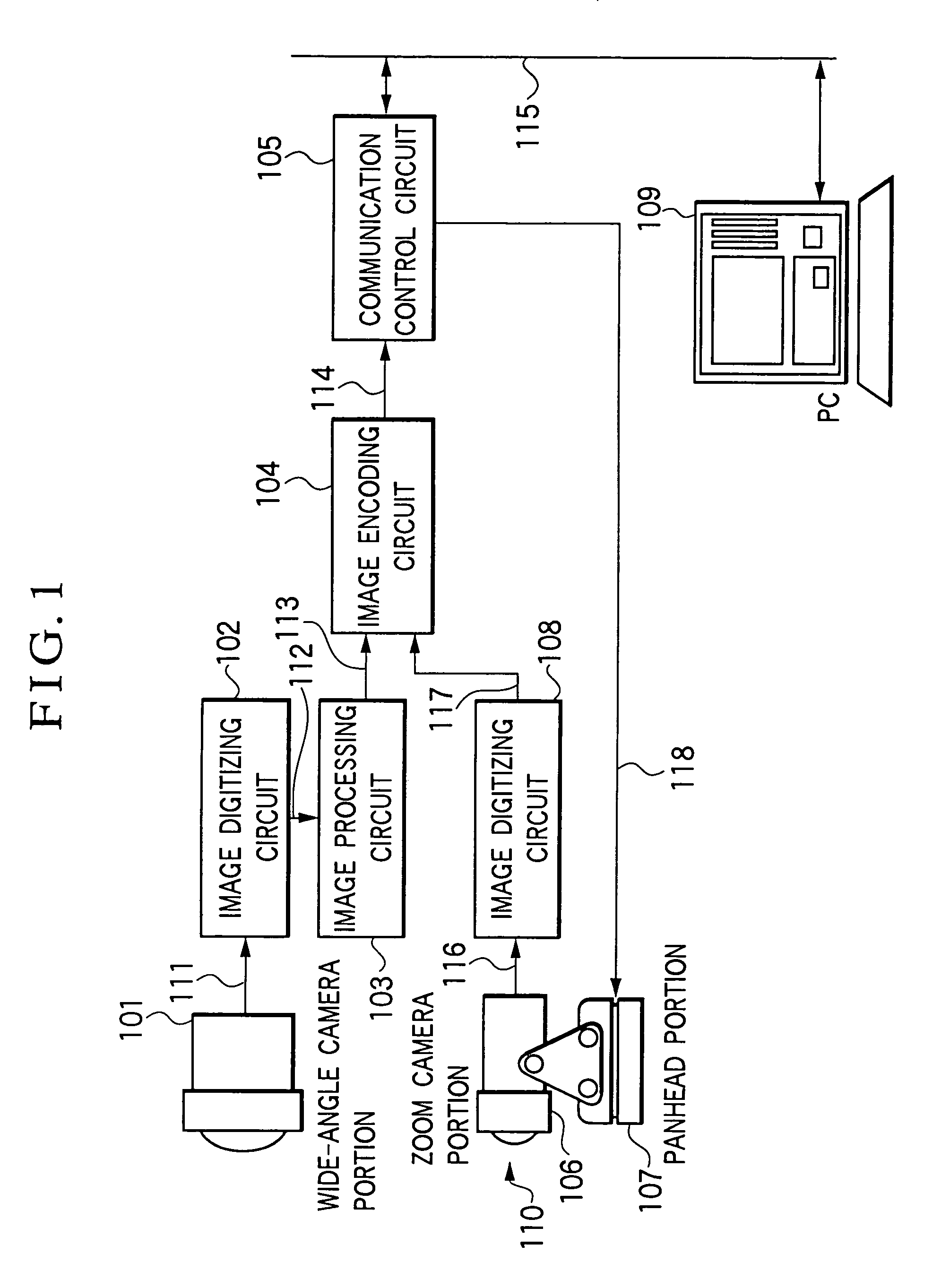
[0041]FIG. 1 is a block diagram showing a camera control system according to a In FIG. 1, reference numeral 101 represents a wide-angle camera portion which can pick up an image at a wide angle of view (field), reference numeral 102 designates an image digitizing circuit for digitizing a video image taken by the wide-angle camera portion 101, reference numeral 103 depicts an image processing circuit for processing the video image digitized, and reference numeral 104 denotes an image encoding circuit for encoding a video image.

[0042]Further, reference numeral 105 signifies a communication control circuit composed a CPU, a memory, a network adapter and others, reference numeral 106 means a zoom camera portion of a camera110 equipped with a panhead, reference numeral 107 indicates a panhead portion of the panhead-mounted camera 110, reference numeral 108 shows an image digitizing circuit for digitizing a video image taken by the panhead-mounted camera 110, and reference numeral 109 re...

second embodiment

[0097]In the second embodiment, two wide-angle camera portions 101 and 601 are fixed in a state of making an angle of 180° therebetween, as shown in FIG. 7. In FIG. 7, reference numerals 71 and 72 designate wide-angle camera portions, respectively, and reference numeral 73 denotes a panhead-mounted camera. The panhead-mounted camera 73 may be constructed to de detachable from the main body.

[0098]Returning again to FIG. 6, a video signal 611 picked up by the wide-angle camera portion 601 is converted into a digital video signal 612 by an image digitizing circuit 602 and is then given to an image processing circuit 603. The image processing circuit 603 image-processes the digital video signal 112 from the image digitizing circuit 102 and the digital video signal 612 from the image digitizing circuit 602 into panoramic images having no distortion, and further combines the panoramic images with each other into one panoramic image and outputs the obtained panoramic image. Incidentally, c...

third embodiment

[0102]FIG. 8 illustratively shows a coaxial camera serving as an optical system of a first apparatus, which is a component of a camera control system according to the invention. In FIG. 8, reference numeral 301 represents a front stage portion which is a lens group serving as a part of each of a wide-angle (fisheye) lens and a telephoto lens, reference numeral 302 designates a first rear stage portion which is a lens group serving as a remaining part of the wide-angle lens, reference numeral 304 depicts a second rear stage portion which is a lens group serving as a remaining part of the telephoto lens, and reference numeral 303 denotes a half mirror disposed at a boundary position between the front stage portion 301 and each of the first rear stage portion 302 and the second rear stage portion 304. Thus, the wide-angle lens (fisheye lens), which has a distortion aberration and permits photography at a wide angle of view, is made up of the front stage portion 301 and the first rear s...


PUM


Abstract

In a camera control system capable of, in a video conference, remote surveillance or the like, issuing an instruction for a camera posture or the like, the user desires, on the moment in a simple way, an image with a small angle of view and a panoramic image are transmitted to a personal computer to be individually displayed. This arrangement constructs a system whereby the user can see not only a detailed image the user desires now but also an image surrounding the detailed image in substantially real time. Further, another arrangement for sensing an image reflected by a convex mirror which is constructed such that a central portion thereof is formed as a low-curvature surface and a peripheral portion thereof is formed as a high-curvature surface enables a panoramic image having a high resolution in a desired portion thereof to be obtained by using only one image sensor.

Description

BACKGROUND OF THE INVENTION[0001]1. Field of the Invention[0002]The present invention relates to a camera control system, and more particularly to a system suitably applicable to video data communication processing systems, such as video conference systems and video surveillance systems, which remotely use moving image data inputted from a camera and processed in a digital processing unit.[0003]2. Description of Related Art[0004]So far, in the fields including video conference systems and surveillance camera systems, their systems are made up of a camera and a user terminal in which parameters or the like of the camera are controllable through a network from a distance, and are composed such that the user remotely controls the camera for receiving and displaying images picked up thereby. Further, as the camera, there has been employed a camera with a panhead which allows variation of the image pickup direction.[0005]This panhead-mounted camera has employed a method of using a dedica...

Claims


Application Information

Patent Timeline
Patent Type & Authority Patents(United States)
IPC IPC(8): G08B13/196H04N5/232H04N7/14H04N7/18
CPCG08B13/19628G08B13/19643G08B13/19682G08B13/19689H04N5/23203H04N5/23206H04N7/142H04N7/181H04N23/66H04N23/661H04N23/631H04N23/635H04N23/695
Inventor SATO, MAMORUSHIRAISHI, AKIHIKO
Owner CANON KK
Why Eureka
Try Eureka