Radiotherapy apparatus

Inactive Publication Date: 2005-12-20
HITACHI LTD
View PDF13 Cites 150 Cited by
  • Summary
  • Abstract
  • Description
  • Claims
  • Application Information

AI Technical Summary

Benefits of technology

[0011]It is an object of the present invention to provide a

Problems solved by technology

Since, however, a doctor or assistant does not confirm the position of a focus by directly viewing the irradiation field before irradiation, the accuracy of irradiation is not high.
Unfortunately, these apparatuses have a structur

Method used


Image

  • Radiotherapy apparatus
  • Radiotherapy apparatus
  • Radiotherapy apparatus

Examples


first embodiment

(First Embodiment)

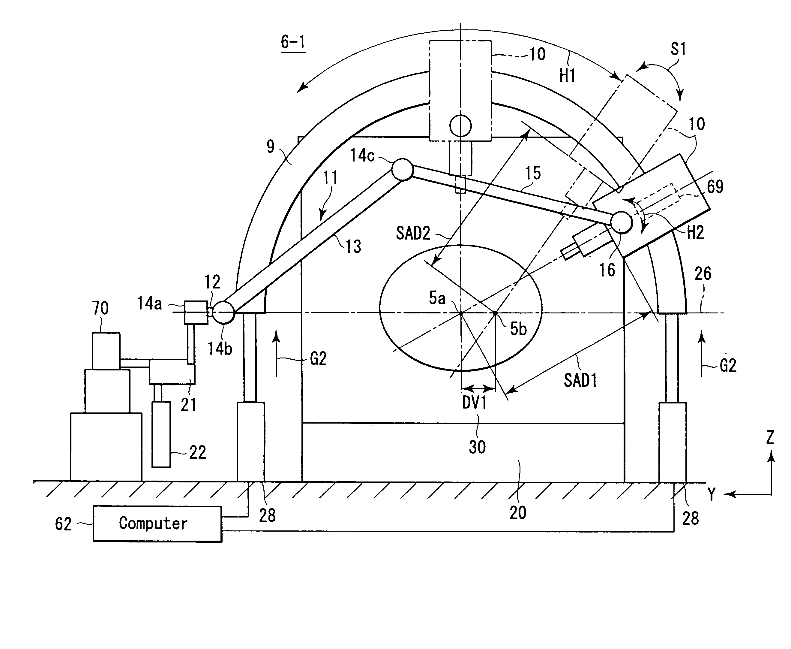
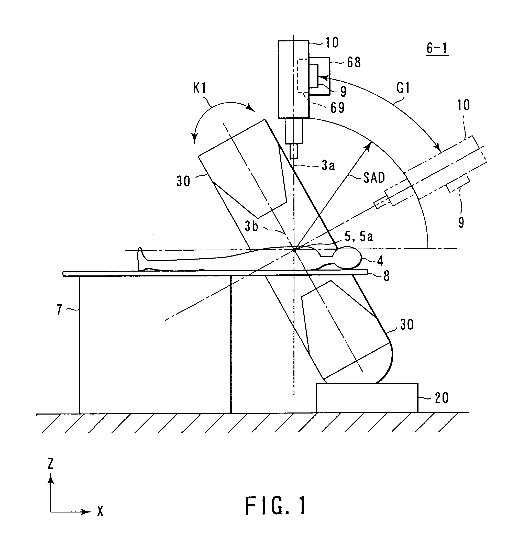
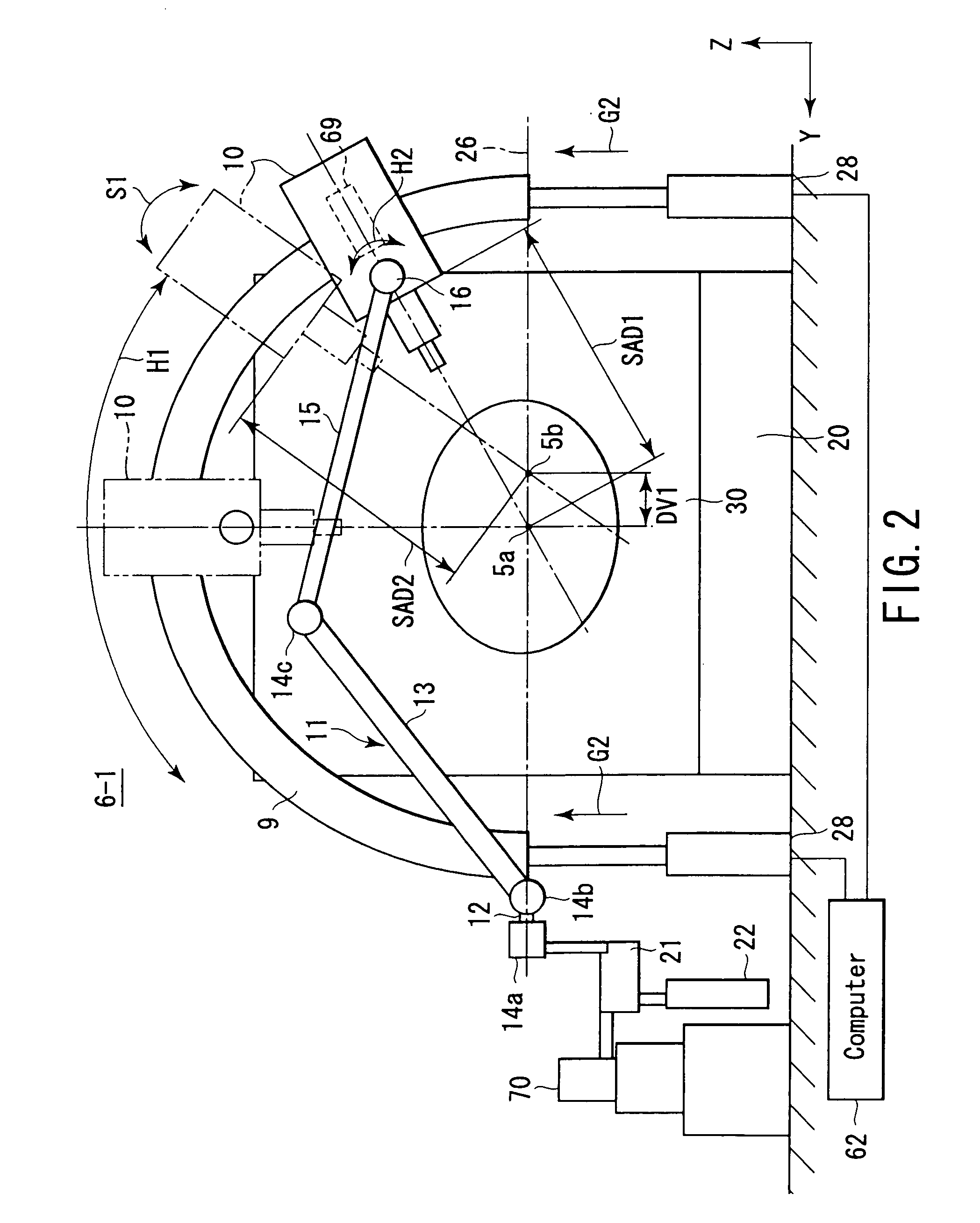
[0057]As shown in FIGS. 1 to 3, a radiotherapy apparatus 6-1 according to this embodiment includes a bed 7 having a top plate 8 on which a patient 4 is placed, an irradiation head 10 for irradiating an irradiation field 5 settable in the patient 4 with therapeutic radiation, and an X-ray CT apparatus 30 for acquiring a tomographic image of the irradiation field 5 as a diseased part.

[0058]Referring to FIG. 1, the top plate 8 can be moved in three axis directions, i.e., a bed longitudinal direction (X-axis direction), bed widthwise direction (Y-axis direction), and bed vertical direction (Z-axis direction), by an X-Y driving mechanism (not shown) contained in the bed 7. Also, the position of this top plate 8 is controlled by a computer system (not shown) on the basis of an image taken by a TV camera (not shown), so that the irradiation field 5 of the patient 4 is positioned in an isocenter 5a. Furthermore, the material and shape of the top plate 8 are so selected as ...

second embodiment

(Second Embodiment)

[0119]A radiotherapy apparatus 6-2 of the second embodiment of the present invention will be described below with reference to FIGS. 10 to 25 in which the same reference numerals as in FIGS. 1 to 9 denote the same parts. FIGS. 10 to 12 correspond to FIGS. 1 to 3, FIG. 18 corresponds to FIG. 8, FIGS. 21 and 22 correspond to FIGS. 5 and 6, and FIG. 25 corresponds to FIG. 9. Therefore, a repetitive explanation of the same portions will be omitted.

[0120]As shown in FIGS. 10 to 12 and 20A to 20D, an irradiation head 1000 of this embodiment is supported by a guide rail 9 by a circumferential moving mechanism 68 and first and second head rotating mechanisms 1310 and 1320. These circumferential moving mechanism 68 and first and second head rotating mechanisms 1310 and 1320 position the irradiation head 1000 in an arbitrary irradiation position within the range of a quarter sphere (half sphere) of the rear portion of the upper half of a sphere around an isocenter 5a.

[0121...

third embodiment

(Third Embodiment)

[0168]A radiotherapy apparatus according to the third embodiment of the present invention will be described below with reference to FIGS. 26 and 27. In FIGS. 26 and 27, a repetitive explanation of the same portions as in the previous figures will be omitted.

[0169]In a radiotherapy apparatus 6-3 of this embodiment, an irradiation head 1000, an image acquiring X-ray source 97 as an X-ray tube of an X-ray CT apparatus, and a sensor array 98 are mounted on a rotary drum 9. The irradiation head 1000 is mounted on a drum of, e.g., a third-generation X-ray CT apparatus. The rotational center of the rotary drum 99 is an isocenter 5a. The irradiation head 1000 is equivalent to an electron linac which generates a radiation of 4 to 10 MeV. As shown in FIGS. 26 and 27, this irradiation head 1000 has head rotating mechanisms having two axes (S1 and S2). By the operations of these head rotating mechanisms, non-isocentric irradiation can be performed around the rotational axis of...


PUM


Abstract

A radiotherapy apparatus comprising an irradiation head having a linear accelerator and an intra-head waveguide unit whose one end portion is electromagnetically connected to the linear accelerator, a supporting moving mechanism which supports and moves the irradiation head on predetermined first spherical coordinates, a microwave oscillator which generates microwaves to be supplied to the irradiation head, and which is placed in a stationary position, a fixed waveguide unit having one end portion electromagnetically connected to the microwave oscillator, and the other end portion positioned on the supporting moving mechanism, and a moving waveguide unit having one end portion electromagnetically connected to the other end portion of the fixed waveguide unit positioned on the supporting moving mechanism.

Description

CROSS-REFERENCE TO RELATED APPLICATIONS[0001]This is a Continuation Application of PCT Application No. PCT / JP02 / 08505, filed Aug. 23, 2002, which was not published under PCT Article 21(2) in English.[0002]This application is based upon and claims the benefit of priority from the prior Japanese Patent Applications No. 2001-254891, filed Aug. 24, 2001; and No. 2001-254892, filed Aug. 24, 2001, the entire contents of both of which are incorporated herein by reference.BACKGROUND OF THE INVENTION[0003]1. Field of the Invention[0004]The present invention relates to a radiotherapy apparatus suited to performing, e.g., radiotherapy on a tumor by a stereotactic pluridirectional irradiation method.[0005]2. Description of the Related Art[0006]A stereotactic pluridirectional irradiation method is one radiotherapy method capable of increasing the therapeutic effect by intensively irradiating a diseased part with radiation in multiple directions, and minimizing the exposure dose of the surroundin...

Claims


Application Information

Patent Timeline
IPC IPC(8): A61B19/00A61N5/02A61N5/10
CPCA61N5/10A61N5/1049A61N5/1081A61N5/1082A61B2019/207A61N5/1037A61N2005/1061A61B2090/101
Inventor YAMASHITA, ICHIROKAMINO, YUICHIROWAKAMOTO, IKUOMIHARA, KAZUMASA
Owner HITACHI LTD
Why Eureka
Try Eureka