Portable cleaning apparatus and method for single pass plate and frame heat exchangers

Inactive Publication Date: 2005-12-27
PHEX
View PDF12 Cites 27 Cited by
  • Summary
  • Abstract
  • Description
  • Claims
  • Application Information

AI Technical Summary

Benefits of technology

[0013]It is yet another object of the present invention to provide a portable apparatus and method for cleaning plate and fram

Problems solved by technology

This reduces the thermal efficiency of the heat exchanger.
Dirt, microbiological material, iron oxide deposits, scale, and process contaminants will negatively impact almost any piping system if left to accumulate, including plate and frame heat exchangers.
This procedure is time consuming and can easily take several days to complete when the heat exchanger contains several hundred plates.
The pressure wash will remove many fouling deposits completely, but there are also many types of deposits that cannot be easily washed away.
Moreover, other drawbacks to physical pressure washing may be realized.
Debris on the gasket surface, even of a small nature, can cause the heat exchanger to leak when it is subsequently assembled and ready for operation.
Furthermore, a brazed-type plate heat exchanger cannot be taken apart and cleaned in this manner.
Problematically, unless a large high-pressure pump is used to force the chemical solution through the plate and frame heat exchanger, there is generally an insufficient flow rate that prevents the cleaning solution from reaching the opposite end of the heat exchanger.
This would also require a large footprint in the mechanical room, and would not be portable to an

Method used


Image

  • Portable cleaning apparatus and method for single pass plate and frame heat exchangers
  • Portable cleaning apparatus and method for single pass plate and frame heat exchangers
  • Portable cleaning apparatus and method for single pass plate and frame heat exchangers

Examples


Embodiment Construction

)

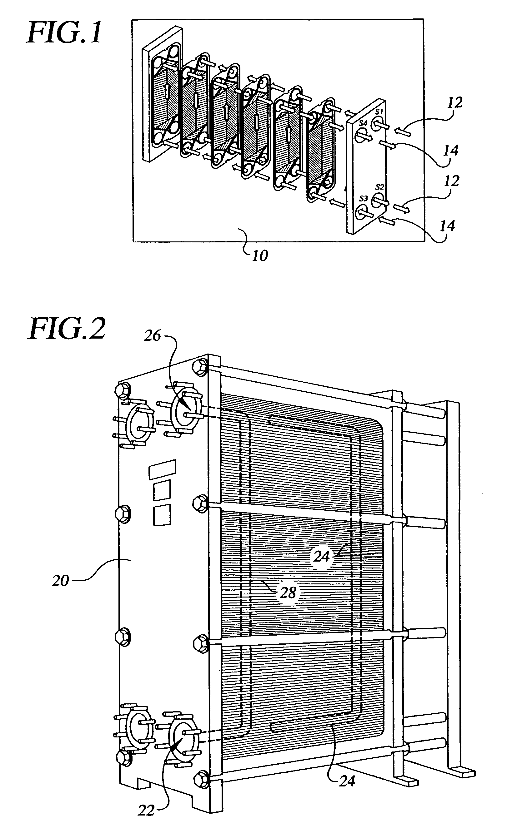
[0028]In describing the preferred embodiment of the present invention, reference will be made herein to FIGS. 1–9 of the drawings in which like numerals refer to like features of the invention.

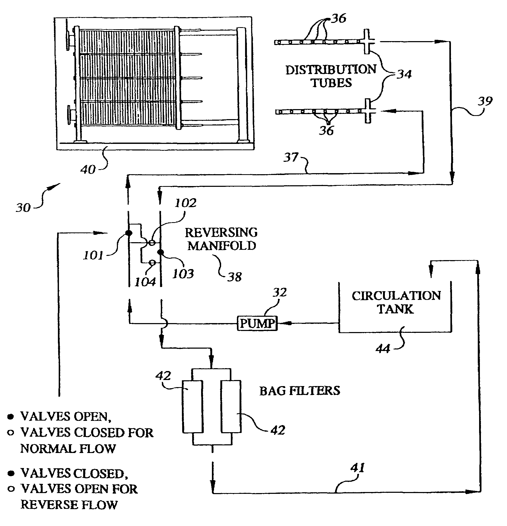
[0029]The present invention provides for a portable apparatus and method for chemically cleaning a single pass plate and frame heat exchanger that allows the cleaning solution to be uniformly distributed across the plate pack. FIG. 3 depicts the smaller, portable cleaning apparatus employed in the present invention for the chemical cleaning of heat exchangers. This portable system 30 attaches to a plate and frame heat exchanger 40 and comprises one pump 32 of preferably 10-horsepower, capable of 300 gallons per minute flow through a discharge port approximately 2 inches in diameter; at least two distribution / collection tubes 34 approximately 2 inches in diameter and having apertures 36 of predetermined diameter and predetermined placement; one reversing manifold 38; two filters 42, preferably...


PUM


Abstract

A portable apparatus and method for chemically cleaning a single pass plate and frame heat exchanger allows the cleaning solution to be uniformly distributed across the plate pack. This portable system of one pump of preferably 10-horsepower, capable of 300 gallons per minute flow through a discharge port; at least two distribution/collection tubes with apertures of predetermined diameter and predetermined placement; one reversing manifold; two bag filters; and one circulation tank with a capacity at least on the order of 150 to 200 gallons; attaches to a single pass plate and frame heat exchanger. The single pass plate and frame heat exchanger is configured with at least two removable flanges that, once removed, allow for the installation of the distribution/collection tubes. The apertures in the distribution/collection tubes are placed facing downwards depending upon the direction of the operational fluid to enhance a vacuuming effect for particle and debris removal during cleaning. The distribution/collection tubes are skewed off-center of the flanges, with an ability to be rotated in at least four different directions off-center, and generally located towards the bottom of the single pass plate and frame heat exchanger to facilitate particulate removal and uniform distribution of cleaning solution.

Description

BACKGROUND OF THE INVENTION[0001]1. Field of the Invention[0002]The present invention relates to single pass plate and frame heat exchangers, and more specifically to an apparatus and method for chemically cleaning a single pass plate and frame heat exchanger without disassembly, with the use of portable, lightweight equipment.[0003]2. Description of Related Art[0004]Heat exchangers have been used to provide for domestic hot water, and in commercial, industrial, process, marine, aquaculture, HVAC, heat recovery, refrigeration, food and beverage processing, pharmaceutical, clean room, and many other applications for many years. One of the most common types of heat exchangers is the plate and frame heat exchanger. A plate and frame heat exchanger is generally comprised of a gasketed plate and frame construction. Gasketed plate and frame heat exchangers have a series of channeled plates that are mounted in a frame and clamped together. Each plate is commonly made from pressable materia...

Claims


Application Information

Patent Timeline
IPC IPC(8): B08B9/00F28F3/08F28G9/00
CPCF28F3/083F28G9/00
Inventor KRUEGER, KURT
Owner PHEX
Why Eureka
Try Eureka