Fuel cell powered electric vehicle

a fuel cell and electric vehicle technology, applied in the direction of cell components, battery/fuel cell control arrangement, propulsion by batteries/cells, etc., can solve the problems of increased volume, weight and cost of the whole system of the fuel cell system, long high voltage wiring connecting the fuel cell and the electricity storage device, and complicated wiring layout, etc., to achieve short high voltage wiring length, light weight and small size

Inactive Publication Date: 2005-12-27
HONDA MOTOR CO LTD
View PDF20 Cites 90 Cited by
  • Summary
  • Abstract
  • Description
  • Claims
  • Application Information

AI Technical Summary

Benefits of technology

[0006]It is an object of the invention to provide a fuel cell powered electric vehicle which can make the fuel cell and the electricity storing device for storing electricity generated by the fuel cell lighter in weight and smaller in size, the high voltage wiring shorter in length and the production costs lower. Further, the fuel cell powered electric vehicle can allow the fuel cell and the electricity storing device to be cooled effectively.
[0013]According to the first aspect of the invention, the fuel cell and the electricity storing device can be disposed via a plate in the box under a cabin, whereby the weight, size and costs of the fuel cell and the electricity storing device can be made lighter, smaller and lower, respectively. Furthermore, the length of the high voltage wiring connecting between the fuel cell and the electricity storing device can be made shorter. The electric power loss can also be made smaller by disposing the fuel cell and the electricity storing device in the common box.
[0014]Furthermore, the electricity storing device controlled at relatively lower temperature than the fuel cell can be cooled by the air within the cabin. The fuel cell controlled at relatively higher temperature than the electricity storing device. The fuel cell is controlled at temperature, which is different from the electricity storing device. Therefore, the fuel cell can be cooled by a separate cooling line, whereby the fuel cell and the electricity storing device can effectively cooled to there own controlled temperatures.
[0015]In addition, the fuel cell and the electricity storing device can be protected against damage by external force by disposing them in the common box.
[0017]According to the second aspect of the invention, proper heat insulation can be provided between the fuel cell and the electricity storing device which have the different controlled temperatures, since the heat insulating material is included in the plate. The cooling efficiency can be improved to there by provide an effective cooling. In other words, even when the fuel cell and the electricity storing device are disposed close and adjacent to each other via the plate, since influence of heat generated by the fuel cell on the electricity storing device or vice versa is interrupted by the separation including the heating insulating material, temperature controls at different temperature bands can easily be implemented.

Problems solved by technology

There is caused a problem that the volume, weight and costs of the whole system of the fuel cell system are increased, since the fuel cell and the electricity storing device are disposed away from each other at the different locations.
In addition, the high voltage wiring connecting between the fuel cell and the electricity storing device is forced to be long.
Therefore, the layout of the wiring becomes complex.
The electric power of the fuel cell system loss is increased.

Method used


Image

  • Fuel cell powered electric vehicle
  • Fuel cell powered electric vehicle
  • Fuel cell powered electric vehicle

Examples


Embodiment Construction

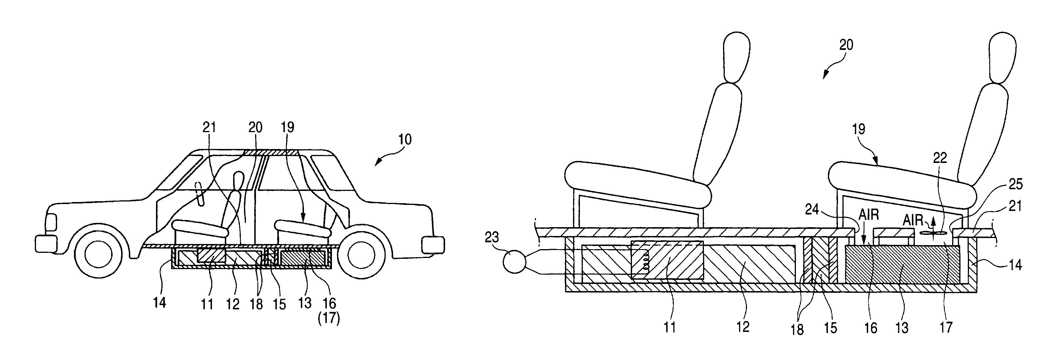
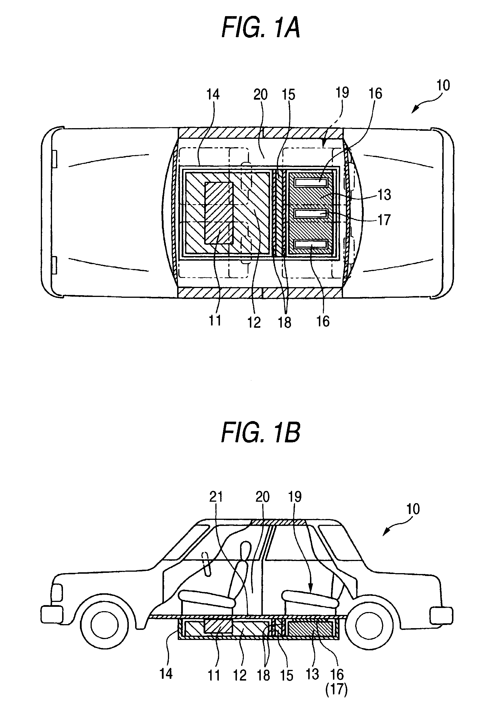
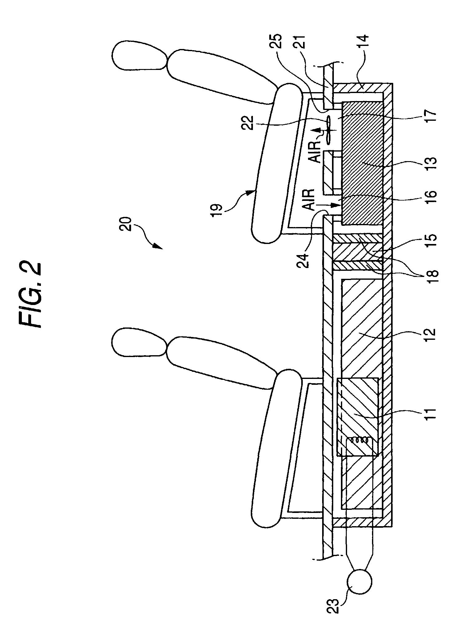
[0028]Referring to the accompanying drawings, an embodiment of a fuel cell powered electric vehicle according to the invention will be described. FIG. 1 shows an arrangement of a fuel cell system and an electricity storing device of a fuel cell powered electric vehicle according to an embodiment of the invention, in which FIG. 1A is a plan view and FIG. 1B is a left side view of the vehicle. As shown in FIG. 1, in a fuel cell powered electric vehicle 10 having a fuel cell system 12 including a fuel cell stack 11 constituted by a plurality of stacked flat plate-like fuel cells and an electricity storing device 13 for storing electricity generated by the fuel cell system 12, the fuel cell system 12 and the electricity storing device 13 are stored in a common box 14 and are disposed under a floor 21 of a cabin 20, and a plate 15 is provided to separate the fuel cell system 12 and the electricity storing device 13 stored in the interior of the box 14 from each other. Furthermore, heat i...


PUM

PropertyMeasurementUnit
temperatureaaaaaaaaaa

Abstract

In a fuel cell powered electric vehicle having a fuel cell system and an electricity storing device for storing electricity generated by the fuel cell system, the fuel cell system and the electricity storing device stored in a box are fixed to a lower side of a floor of a cabin. A plate is provided to separate the fuel cell system and the electricity storing device in the interior of the box from each other. In addition, through holes are provided in the floor of the cabin for connecting between a refrigerant inlet port and a refrigerant outlet port of the electricity storing device and the cabin.

Description

FIELD OF THE INVENTION[0001]The present invention relates to a fuel cell powered electric vehicle having a fuel cell and an electricity storing apparatus for storing electricity generated by the fuel cell, and more particularly to the fuel cell powered electric vehicle having a structure in which a plate are interposed between the fuel cell and the electricity storing device.DESCRIPTION OF THE RELATED ART[0002]Conventionally, in fuel cell powered electric vehicles, a fuel cell stack which is controlled at a high temperature, is disposed at a front nose part or under a cabin. The electricity storing device for temporarily storing electricity generated by the fuel cells is disposed separately from the fuel cell stack at a different location such as a trunk at a rear part of the vehicle since the device is controlled at a low temperature.[0003]FIG. 3 shows an arrangement of the fuel cell and the electricity storing device on a fuel cell powered electric vehicle (hereinafter, also refer...

Claims


Application Information

Patent Timeline
Patent Type & Authority Patents(United States)
IPC IPC(8): B60K1/00B60K11/00B60K11/06B60L50/64B60R16/04H01G2/08H01M2/10H01M8/00H01M8/04H01M10/60H01M10/613H01M10/625H01M10/6565H01M10/658H01M16/00
CPCB60K1/04B60L11/1881B60L11/1892B60L11/1894H01G2/08H01M2/1072H01M2/1094H01M10/5004H01M10/5016H01M10/5067H01M10/5087H01M10/5093H01M16/006H01G11/10B60K2001/005H01M8/04029H01M16/003H01M2250/20Y02T10/7022Y02T90/16Y02T90/34Y02T90/32Y02E60/13H01M10/625H01M10/6563H01M10/66H01M10/613H01M10/658B60L58/30B60L58/33B60L58/34Y02T10/70Y02T90/40Y02E60/50Y02E60/10H01M50/24H01M50/249B60L50/64H01M50/202
Inventor KUBOTA, SHINYAMATSUOKA, TOSHIYUKIMITA, YOSHINORI
Owner HONDA MOTOR CO LTD
Why Eureka
Try Eureka