Temperature probe and thermometer having the same

a temperature probe and thermometer technology, applied in the field of thermometers, can solve the problems of slow time response, less exponentially, high circuit complexity, etc., and achieve the effect of dramatic reduction of measurement tim

Inactive Publication Date: 2005-12-27
MESURE TECH
View PDF26 Cites 10 Cited by
  • Summary
  • Abstract
  • Description
  • Claims
  • Application Information

AI Technical Summary

Benefits of technology

[0012]In close contact with flesh in a body cavity, the thermal contact surface serves as a heater such that the thermal sensor or transmission w

Problems solved by technology

However, the major concern with regard to the electronic thermometers lays on their slow time response.
This problem is incurred mainly because a thermometer probe represents a certain amount of mass and heat capacity, and when inserted from room temperature into a body cavity it cannot change temperature instantaneously, but instead approaches its final temperature more or less exponentially.
Nevertheless, these thermometers have some

Method used


Image

  • Temperature probe and thermometer having the same
  • Temperature probe and thermometer having the same
  • Temperature probe and thermometer having the same

Examples


first embodiment

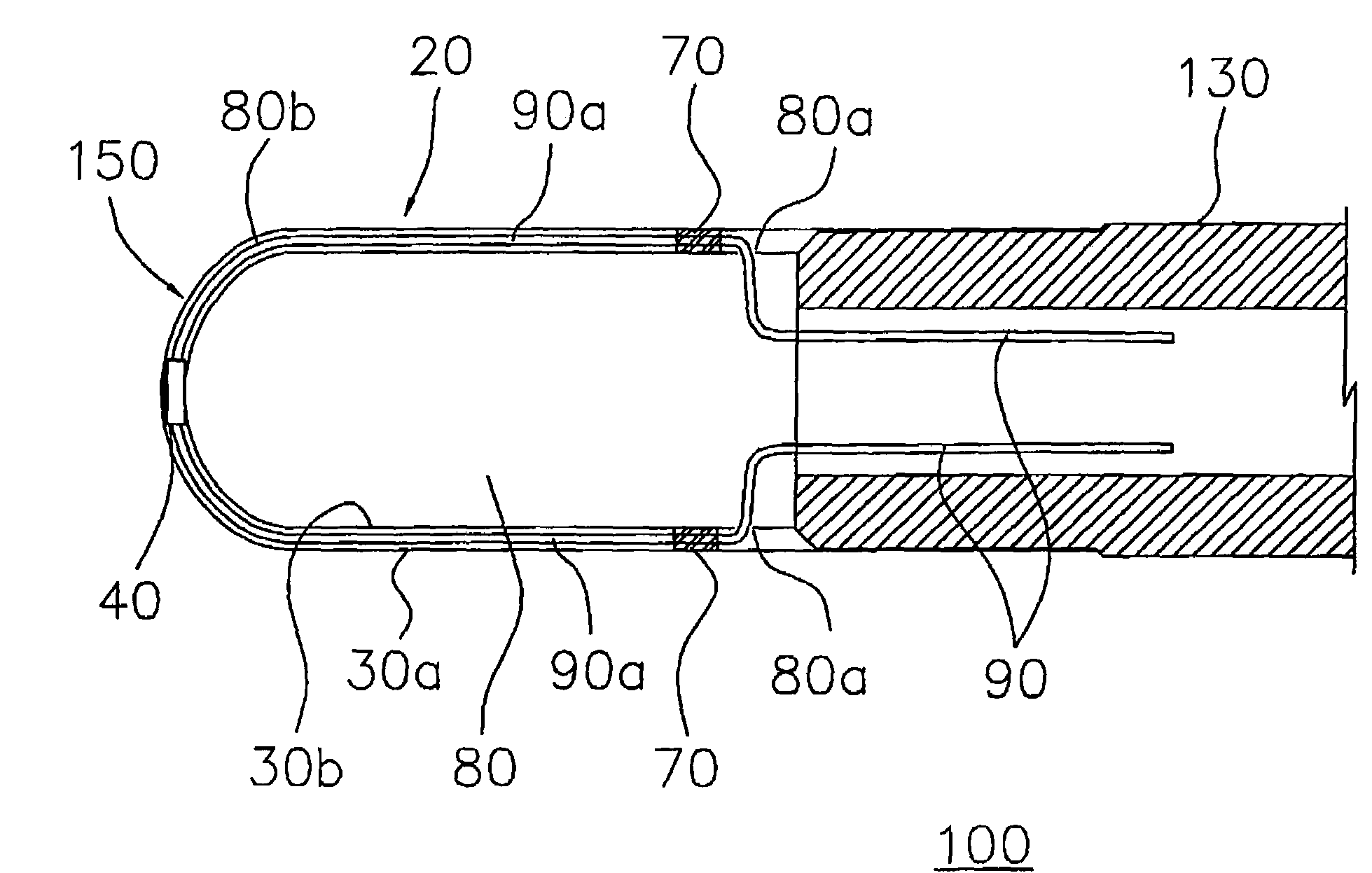
[0026]Referring to FIG. 3, a temperature probe 100 of the invention is illustrated. The temperature probe 100 includes a probe body 130 and a hollow tip member 20 secured to the probe body 130. The hollow tip member 20 has an outer wall 30a as a thermal contact surface 30 and an inner wall 30b inside the outer wall 30a. A thermal isolation space 80b is formed between the outer wall 30a and the inner wall 30b. A hollow cavity 80 is surrounded by the inner wall 30b. A thermal sensor 40 is disposed within the hollow tip member 20. For example, the thermal sensor 40 is disposed within the thermal isolation space 80b. Preferably, the thermal sensor 40 is placed at the front end 150 of the hollow tip member 20 and mounted on the inside of the outer wall 30a. The thermal sensor 40 senses the temperature of the thermal contact surface and produces a temperature signal. A set of transmission wires 90 is connected to the thermal sensor to pass the temperature signal. Preferably, at least a po...

second embodiment

[0027]FIG. 4 is a thermometer 10 with a temperature probe according to the invention. The thermometer 10 includes an integrated and inseparable body member 140 plus a hollow tip member 20. In FIG. 4 the hollow tip member 20 is shown in an enlarged view for detailed description. The body member 140 is comprised of a probe portion 140a and a display portion 140b. The hollow tip member 20 is secured to the probe portion 140a. The hollow tip member 20 has an outer wall 30a as a thermal contact surface 30 and an inner wall 30b inside the outer wall 30a. A thermal isolation space 80b is formed between the outer wall 30a and the inner wall 30b. A hollow cavity 80 is surrounded by the inner wall 30b. A thermal sensor 40 is disposed within the hollow tip member 20. The thermal sensor 40 senses the temperature of the thermal contact surface and produces a temperature signal. A set of transmission wires 90 is connected to the thermal sensor to pass the temperature signal. Preferably, at least ...

third embodiment

[0029]Turning now to FIG. 5, a thermometer 10 having a temperature probe is illustrated. The thermometer 10 includes a separable body member 150 and a hollow tip member 20. In FIG. 5 the hollow tip member 20 is shown in an enlarged view for detailed description. The body member 150 is made up of an independent probe body 152 and an independent display body 154. A hollow tip member 20 is secured to the probe body 152. The hollow tip member 20 has an outer wall 30a as a thermal contact surface 30 and an inner wall 30b inside the outer wall 30a. A thermal isolation space 80b is formed between the outer wall 30a and the inner wall 30b. A hollow cavity 80 is surrounded by the inner wall 30b. A thermal sensor 40 is disposed within the hollow tip member 20. The thermal sensor 40 senses the temperature of the thermal contact surface and produces a temperature signal. A set of transmission wires 90 is connected to the thermal sensor to pass the temperature signal. For example, at least a por...


PUM


Abstract

A temperature probe for use in a medical thermometer. The temperature probe includes a probe body and a hollow tip member secured to the probe body. The hollow tip member further has an outer wall as a thermal contact surface, an inner wall inside the outer wall, a thermal isolation space formed between the outer wall and the inner wall, and a hollow cavity surrounded by the inner wall. A thermal sensor is disposed within the hollow tip member so as to sense the temperature of the thermal contact surface and produce a temperature signal. A set of transmission wires is connected to the thermal sensor to pass the temperature signal.

Description

CROSS REFERENCE TO RELATED APPLICATIONS[0001]This application is a Continuation-In-Part of U.S. patent application Ser. No. 10 / 274,220, filed Oct. 18, 2002, now abandoned.BACKGROUND OF THE INVENTION[0002]1. Field of the Invention[0003]The invention relates to the field of thermometers. More particularly, the invention relates to the field of medical thermometers employing a temperature probe for measurement of a patient's temperature, although it is equally applicable to other temperature measurement fields.[0004]2. Description of the Related Art[0005]As disclosed in U.S. Pat. No. 4,183,248, electronic thermometers offer a great number of advantages over conventional glass and mercury thermometer for use in the health care field. Among the advantages of electronic thermometers are the elimination of sterilization procedure for glass thermometers, a digital temperature display to eliminate temperature reading errors, and higher accuracy and resolution, e.g., 1 / 10 degree Fahrenheit, b...

Claims


Application Information

Patent Timeline
IPC IPC(8): G01K1/18G01K13/00
CPCG01K1/18G01K13/002G01K13/20
Inventor CHANG, HSIAO YIYU, CHU YIH
Owner MESURE TECH
Why Eureka
Try Eureka