

Lithium secondary battery and positive electrode for lithium secondary battery
a lithium secondary battery and positive electrode technology, applied in the manufacture process of electrodes, cell components, electrochemical generators, etc., can solve the problems of difficult to break the entire thin film, small decrease in capacity, etc., and achieve excellent charge-discharge cycle characteristics and high discharge capacity
- Summary
- Abstract
- Description
- Claims
- Application Information
AI Technical Summary
Benefits of technology
Problems solved by technology
Method used
Image

Examples
experiment 1
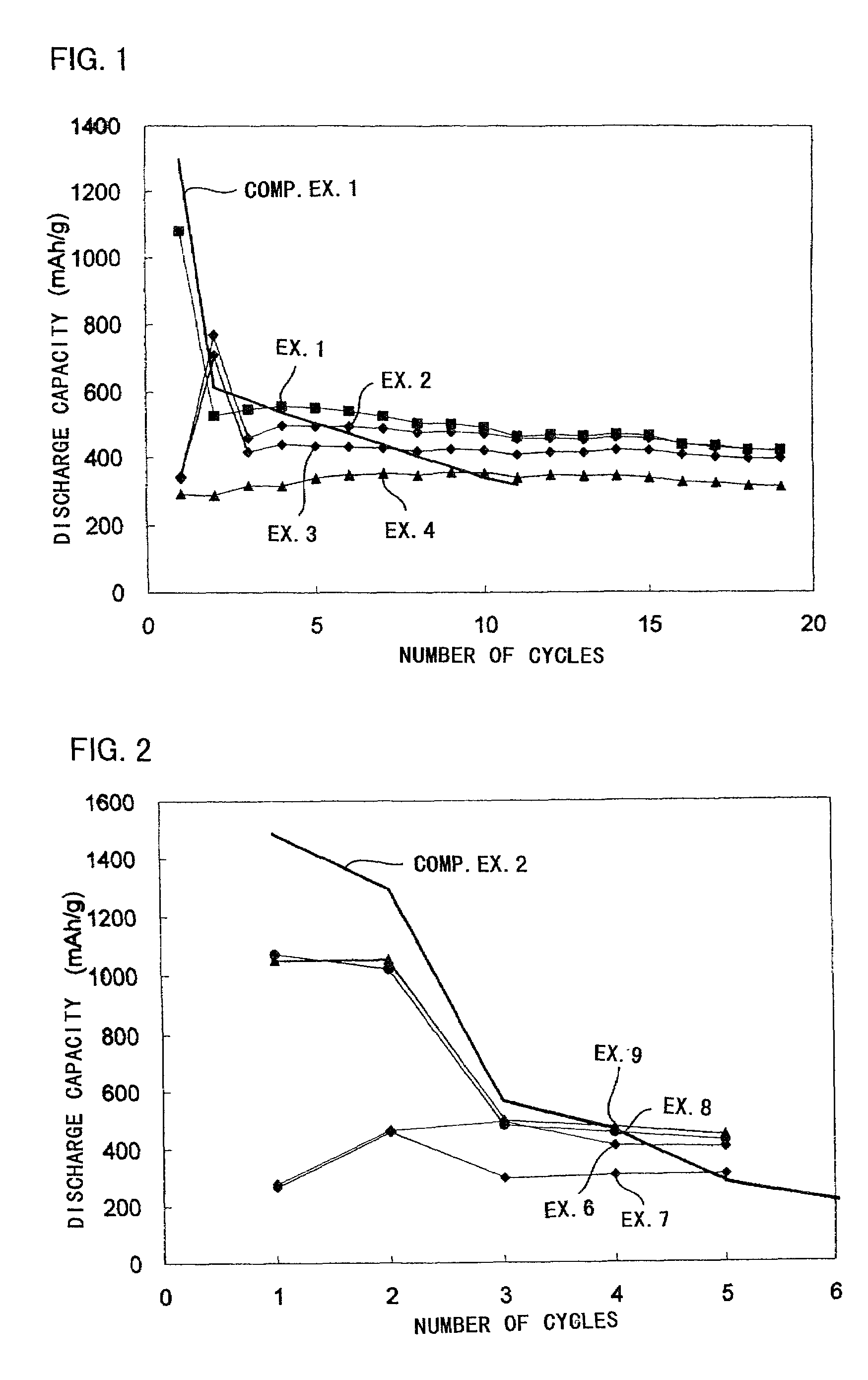
(Experiment 1)
[Production of Positive Electrode]
[0040]A thin film was formed on an aluminum foil (the thickness of 20 μm) using a target of K1.33Fe11O17 by RF sputtering method. The film forming conditions were shown in Table 1.
[0041]As the target shown in Table 1, those with a diameter of 10.2 cm (4 inch) and a thickness of 5 mm were employed. As the carbon chips put on the targets, those with a diameter of 10 mm and a thickness of 1 mm, and as the iron chips, those with 10 mm square and a thickness of 1 mm were employed in the number shown in Table 1, respectively. As the carbon chips, pellets made from powdery graphite were employed. As the iron chips, iron plates with the above-described shapes were employed.
[0042]
TABLE 1loadedsputteringsputteringelectricgas flowgas flowtargetchippowerrate Arrate O2Ex. 1K1.33Fe11O17none350 W100 sccm0 sccmEx. 2K1.33Fe11O173 carbon350 W100 sccm0 sccmchipsEx. 3K1.33Fe11O178 carbon350 W100 sccm5 sccmchipsEx. 4K1.33Fe11O178 iron350 W100 sccm5 sccmchi...
experiment 2
(Experiment 2)
[Production of Positive Electrode]
[0056]A thin film (a ferrite thin film) constituted of Fe and O was produced on an aluminum foil (the thickness of 20 μm) by a reactive deposition method. In the reactive deposition method, O2 was introduced into a vacuum chamber and the Fe deposition material was melted and evaporated by an electron beam (EB) gun to form the ferrite thin film on the aluminum foil, i.e. a substrate (Examples 5–7).
[0057]Further, also by an ion-assisting reactive deposition method, in which simultaneously with the deposition of Fe, ion beam was radiated toward the aluminum foil, an iron oxide (ferrite) thin film was formed (Examples 8 and 9).
[0058]Table 3 shows the respective film forming conditions.
[0059]
TABLE 3film-depositionreactiveion beamformingdepositionspeedgas O2radiationmethodmaterial(nm / sec.)flow rateconditionsEx. 5reactiveFe0.25–0.4010 sccmno radiationEx. 6deposition0.20–0.3020 sccmEx. 7method0.30–0.4030 sccmEx. 8ion beam-0.40–0.5030 sccmAr 4 ...
PUM
| Property | Measurement | Unit |
|---|---|---|
| thickness | aaaaa | aaaaa |
| thickness | aaaaa | aaaaa |
| diameter | aaaaa | aaaaa |
Abstract
Description
Claims
Application Information