Process endpoint detection method using broadband reflectometry

a reflectometry and endpoint technology, applied in the direction of semiconductor/solid-state device testing/measurement, individual semiconductor device testing, instruments, etc., can solve the problem of difficult to determine how far down to etch the polysilicon to make the required recess depth, and the accuracy of forming the desired depth is difficul

Inactive Publication Date: 2005-12-27
LAM RES CORP
View PDF22 Cites 41 Cited by
  • Summary
  • Abstract
  • Description
  • Claims
  • Application Information

AI Technical Summary

Benefits of technology

[0013]In one aspect, the invention relates, to a method of determining a parameter of interest during processing of a patterned substrate which comprises obtaining a measured net reflectance spectrum resulting from illuminating at least a portion of the patterned substrate with a light beam having a broadband spectrum and calculating a modeled net reflectance spectrum as a weighted incoherent sum of reflectances from different regions constituting the portion of the patterned substrate. For wavelengths below a selected transition wavelength in the broadband spectrum, a first optical model is used to calculate the reflectance from each region as a weighted coherent sum of reflected fields from thin film stacks corresponding to laterally distinct areas constituting the region. For wavelengths above the selected transition wavelength in the broadband spectrum, a second optical model is used to calculate the reflectance from each region as a reflected field from a thin film stack obtained by replacing layers in the region with effective homogeneous mediums. The method further includes determining a set of parameters that provides a close match between the measured net reflectance spectrum and the modeled net reflectance spectrum.
[0014]In another aspect, the invention relates to a method for controlling processing of a p...

Problems solved by technology

However, various factors make it challenging to accurately form a recess having a desired depth.
Thus, the dimensional control limits are very tight.
Without knowledge of these variations, it would be difficult to determine how far down to etch the polysilicon to make the required recess depth.
The response of this method is typically delayed because it monitors the plasma state instead of the substrate state.
Optical emission spectroscopy is generally unsuitable for deep trench and recess etching as well as other etch applications where there is no effective etch stop layer.
Single-wavelength interferometric approaches are limited in their ability to monitor etching applications such as recess etching.
Thus, they cannot compensate for incoming material variations from one substrate to another, such as variation in thickness of mask ...

Method used


Image

  • Process endpoint detection method using broadband reflectometry
  • Process endpoint detection method using broadband reflectometry
  • Process endpoint detection method using broadband reflectometry

Examples


Embodiment Construction

[0041]The invention will now be described in detail with reference to a few preferred embodiments, as illustrated in the accompanying drawings. In the following description, numerous specific details are set forth in order to provide a thorough understanding of the invention. It will be apparent, however, to one skilled in the art, that the invention may be practiced without some or all of these specific details. In other instances, well-known process steps and / or features have not been described in detail in order to not unnecessarily obscure the invention. The features and advantages of the invention may be better understood with reference to the drawings and discussions that follow.

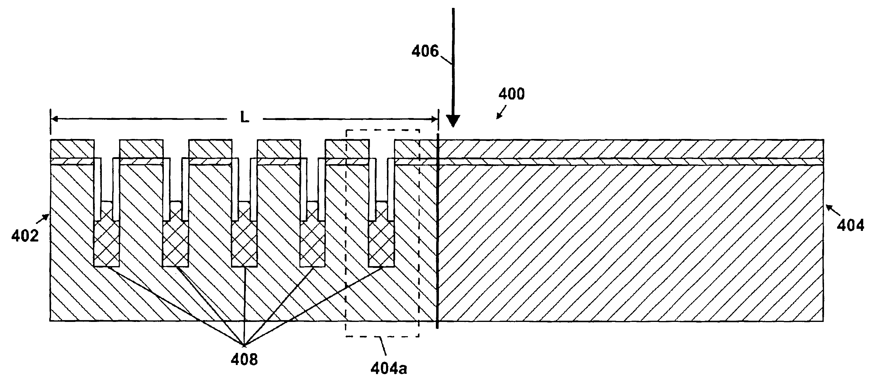
[0042]In one embodiment of the invention, broadband reflectometry is used to measure the reflectance from a patterned substrate while the patterned substrate is being processed. The reflectometry approach involves illuminating the patterned substrate with broadband light and collecting reflectance data...


PUM


Abstract

A method of determining a parameter of interest during processing of a patterned substrate includes obtaining a measured net reflectance spectrum resulting from illuminating at least a portion of the patterned substrate with a light beam having a broadband spectrum, calculating a modeled net reflectance spectrum as a weighted incoherent sum of reflectances from different regions constituting the portion of the patterned substrate, and determining a set of parameters that provides a close match between the measured net reflectance spectrum and the modeled net reflectance spectrum. For wavelengths below a selected transition wavelength, a first optical model is used to calculate the reflectance from each region as a weighted coherent sum of reflected fields from thin film stacks corresponding to laterally distinct areas constituting the region. For wavelengths above the transition wavelength, a second optical model based on effective medium approximation is used to calculate the reflectance from each region.

Description

CROSS REFERENCE TO RELATED APPLICATIONS[0001]This application claims priority from and incorporates by reference the following provisional application(s) entitled “Endpoint Strategies for in situ Control of Recess and Deep Trench Etch Processes,” filed “Aug. 13, 2002” (application Ser. No. 60 / 403,213) by inventor(s) Vijayakumar C. Venugopal and Andrew J. Perry and “Reflectrometry-based Approaches For in situ Monitoring of Etch Depths in Plasma Etching Processes, ” filed Sep. 6, 2002 (application Ser. No. 60 / 408,619) by inventor(s) Vijay C. Venugopal and Andrew J. Perry. This application also claims priority from and incorporates by reference the following non-provisional application(s) entitled “Method for In-Situ Monitoring of Patterned Substrate Processing Using Reflectrometry,” filed Nov. 1, 2002 (application Ser. No. 10 / 286,410) by inventor(s) Vijayakumar C. Venugopal and Andrew J. Perry and “Method for Controlling A Recess Etch Prcoess,” filed Nov. 1, 2002 (application Ser. No....

Claims


Application Information

Patent Timeline
IPC IPC(8): G01B11/06G01N21/84
CPCG01B11/0625G01B11/0683G01N21/8422
Inventor VENUGOPAL, VIJAYAKUMAR C.
Owner LAM RES CORP
Why Eureka
Try Eureka