Appratus for optical analysis of an associated tissue sample

an associated tissue and optical analysis technology, applied in the direction of optical radiation measurement, luminescent dosimeters, diagnostics using spectroscopy, etc., can solve the problem of severe distortion of intrinsic fluorescence spectra

Inactive Publication Date: 2014-05-01
KONINKLIJKE PHILIPS ELECTRONICS NV
View PDF2 Cites 41 Cited by
  • Summary
  • Abstract
  • Description
  • Claims
  • Application Information

AI Technical Summary

Benefits of technology

[0040]According to another embodiment of the invention, there is provided an apparatus wherein a smallest distance d12 between the first light emitter and the first light collector, respectively, and the second light emitter and the second light collector is smaller than the first distance d1 between the first light emitter and the first light collector. A possible advantage of this embodiment may be, that substantially the same volume of the associated tissue sample is analysed, so that the even an inhomogeneous (with respect to a length scale of the order of d1) sample may be correctly analyzed.
[0041]According to another embodiment of the invention, there is provided an apparatus wherein the first light collector coincides with the second light collector, such as the first light collector being the same light collector as the second light collector, such as the first light collector being the same light guide as the second light collector. A possible advantage of this arrangement is that a single light collector may act as both the first light collector and the second light collector, and in this way the number of light collectors is reduced from two to one. Furthermore, using the same light collector as both first and second light collector may enable using the same optical spectrometer comprising the detector for obtaining both the first and second set of data, such as a fluorescence spectrum and a DRS spectrum, without the need for additional optics.

Problems solved by technology

However, the interplay of scattering and absorption usually results in severe distortion of the intrinsic fluorescence spectra.

Method used


Image

  • Appratus for optical analysis of an associated tissue sample
  • Appratus for optical analysis of an associated tissue sample
  • Appratus for optical analysis of an associated tissue sample

Examples


Embodiment Construction

[0085]In the following and throughout this application “light guide” is used interchangeably with “fibre” or “optical fibre”. Furthermore, “source light guide” is used interchangeably with “light emitter”, and “detector light guide” is used interchangeably with “light collector”, and “Reflectance Spectroscopy” is used interchangeably with “Diffuse Reflectance Spectroscopy” (DRS).

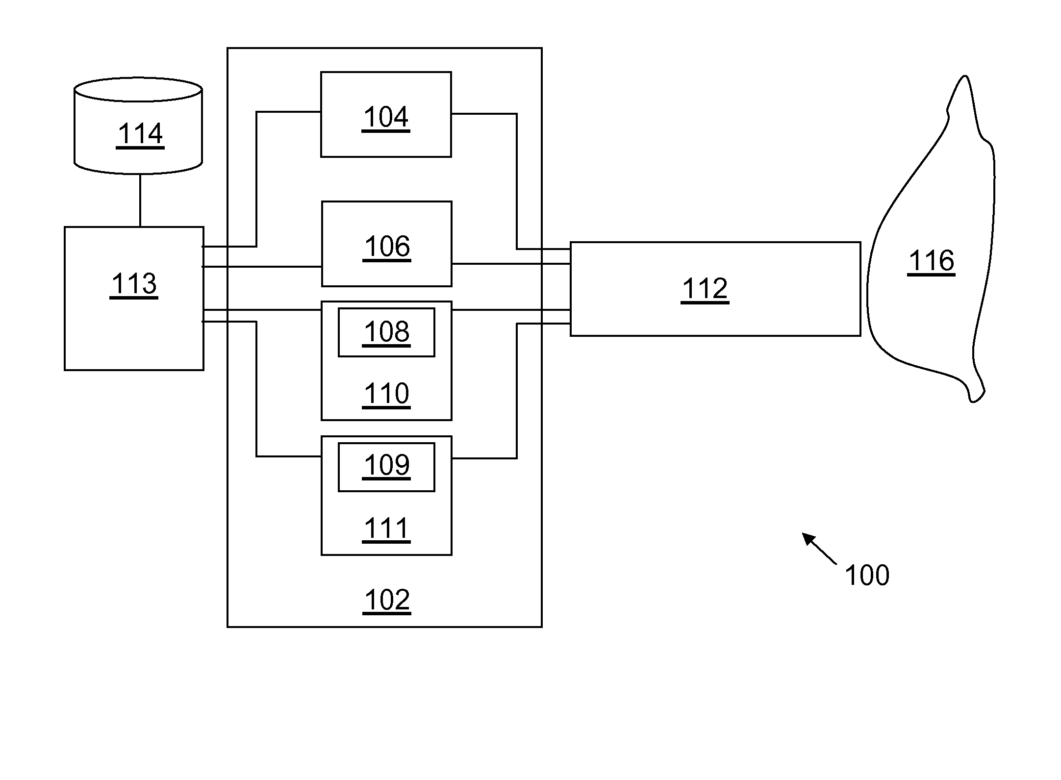
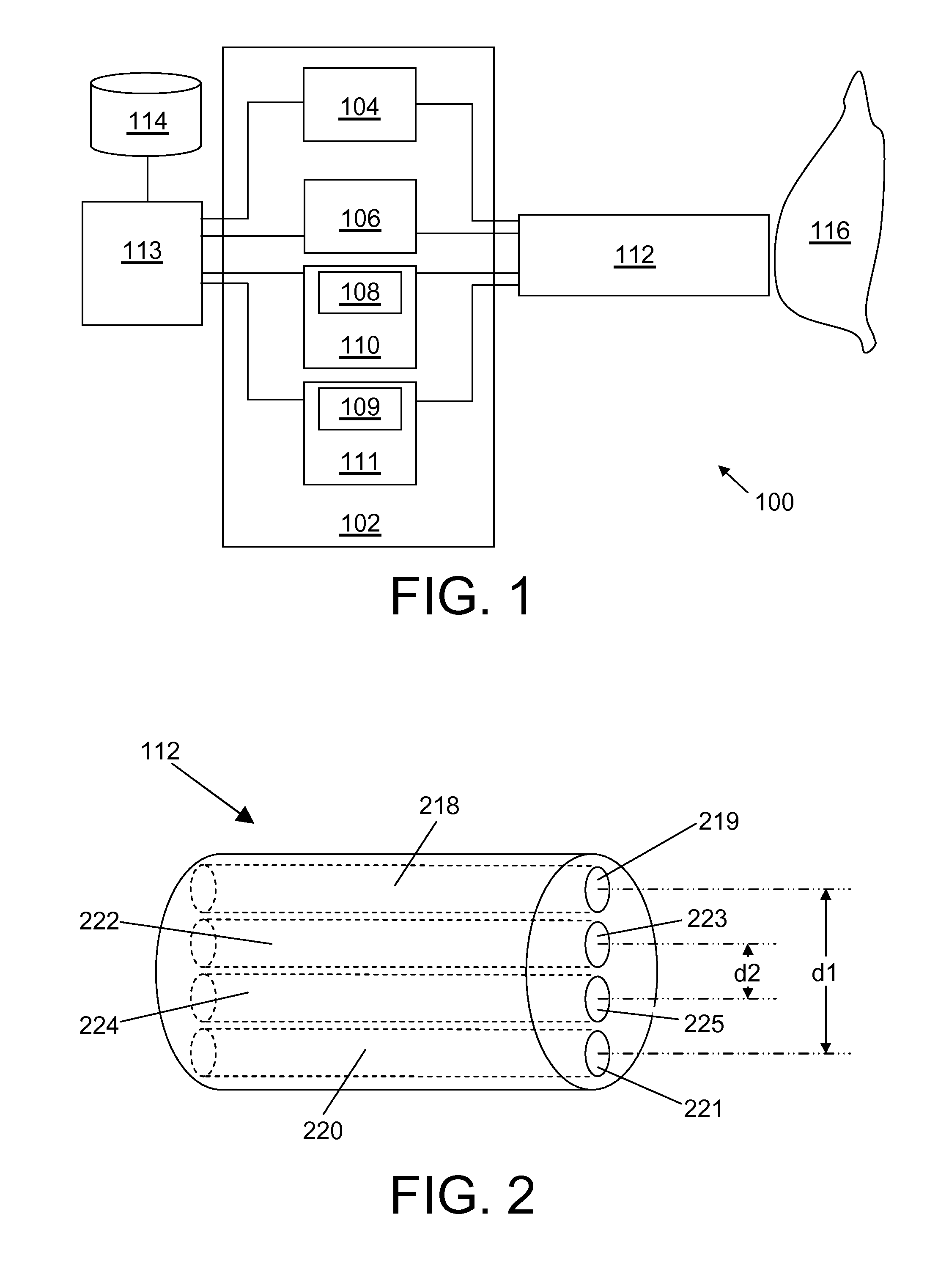
[0086]FIG. 1 shows a schematic of an embodiment of the invention by showing an apparatus 100 according to an embodiment of the invention comprising an optical console 102 comprising a first light source 104, a second light source 106, a first spectrometer 110 comprising a first detector 108 and a second spectrometer 111 comprising a second detector 109. The figure furthermore shows an interventional device 112, where the interventional device 112 has four light guides, where the ends of the four light guides correspond to respectively a first light emitter, a first light collector, a second light emitter and...


PUM


Abstract

In order to improve fluorescence measurements, there is provided an apparatus and, a method and a computer program for optical analysis of an associated tissue sample, the apparatus comprising a spectrometer comprising an optical detector, a light source, a first light emitter 219 arranged for emitting photons into the associated tissue sample, a first light collector 221 arranged for receiving photons from the associated tissue sample, a second light emitter 223, a second light collector 225, wherein a reflectance spectrum is obtained via the first light emitter 219 and collector 221 and a fluorescence spectrum is obtained via the second light emitter 223 and collector 225, and where a first distance d1 between the first light emitter and collector is larger than a second distance d2 between the second light emitter and collector. By combining the data thus obtained, an intrinsic fluorescence spectrum may be obtained.

Description

FIELD OF THE INVENTION[0001]The present invention relates to an apparatus for optical analysis of an associated tissue sample, and more specifically to an apparatus, a method and a computer program for optical analysis of an associated tissue sample.BACKGROUND OF THE INVENTION[0002]Fluorescence spectroscopy can give crucial information about the state of biological tissue, e.g. for cancer detection. However, the interplay of scattering and absorption usually results in severe distortion of the intrinsic fluorescence spectra.[0003]The reference EP 1 942 335 describes an apparatus for optically measuring tissue, the apparatus comprises a radiation source that illuminates a region of interest in tissue to be measured with incident radiation, an optical system that collects scattered and fluorescent light from the tissue at a plurality of wavelengths, a detector system that senses the collected light and provides fluorescence data and scattered light data as a function of wavelength; an...

Claims


Application Information

Patent Timeline
Patent Type & Authority Applications(United States)
IPC IPC(8): A61B5/00
CPCA61B5/0071A61B5/0075A61B5/0084
Inventor MUELLER, MANFREDHENDRIKS, BERNARDUS HENDRIKUS WILHELMUSBIERHOFF, WALTHERUS CORNELIS JOZEFLUCASSEN, GERHARDUS WILHELMUSHORIKX, JEROEN JAN LAMBERTUSNACHABE, RAMIVAN DER VOORT, MARJOLEIN
Owner KONINKLIJKE PHILIPS ELECTRONICS NV
Why Eureka
Try Eureka