Automotive alternating-current dynamoelectric machine

a dynamoelectric machine and alternating-current technology, applied in the direction of dynamo-electric components, windings, magnetic circuit shapes/forms/construction, etc., can solve the problems of increasing the size of the engine compartment of the automobile, little mounting space to spare, and unpleasant noise for human ears

Inactive Publication Date: 2005-12-27
MITSUBISHI ELECTRIC CORP
View PDF16 Cites 22 Cited by
  • Summary
  • Abstract
  • Description
  • Claims
  • Application Information

AI Technical Summary

Benefits of technology

[0018]Therefore, spatial fifth-order harmonics and spatial seventh-order harmonics in the stator can be reduced, thereby providing an automotive alternating-current dynamoelectric machine enabling 6f electromagnetic vibrational force, which is a factor in the generation of unpleasant noise and vibration, to be reduced.

Problems solved by technology

In recent years, improvements in power output are being demanded of automotive alternating-current dynamoelectric machines due to increases in automotive vehicle loads while on the other hand, automotive vehicle engine compartments are becoming increasingly smaller, leaving little mounting space to spare.
Higher harmonic electromagnetic noise in a normal service region from an idling state in which engine rotational speeds are low has a particularly different frequency from the noise of the engine and auxiliary machinery and is heard as a noise that is unpleasant to human ears.
Thus, one problem has been that electromagnetic noise due to the harmonic components of this 6f electromagnetic vibrational force is large, subjecting passengers to unpleasant sensations.
In such cases, another problem has been that vibrations due to the 6f electromagnetic vibrational force are transmitted to the belt, reducing the service life of the belt.
During inverter mode at low rotational speeds, where electric power supply is controlled by an inverter unit, since the harmonic components of the 6f electromagnetic vibrational force correspond to the resonance points of the stator, another problem has been that deterioration of the belt service life is particularly promoted.

Method used


Image

  • Automotive alternating-current dynamoelectric machine
  • Automotive alternating-current dynamoelectric machine
  • Automotive alternating-current dynamoelectric machine

Examples


embodiment 1

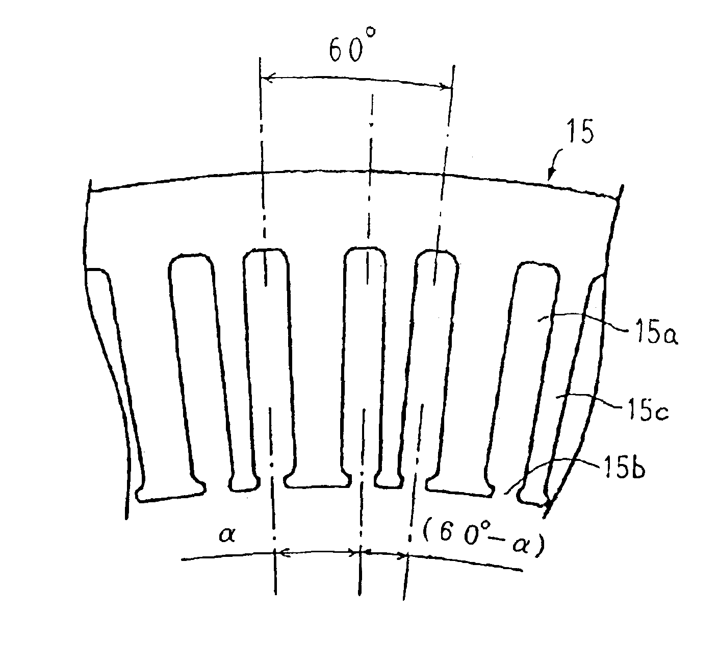
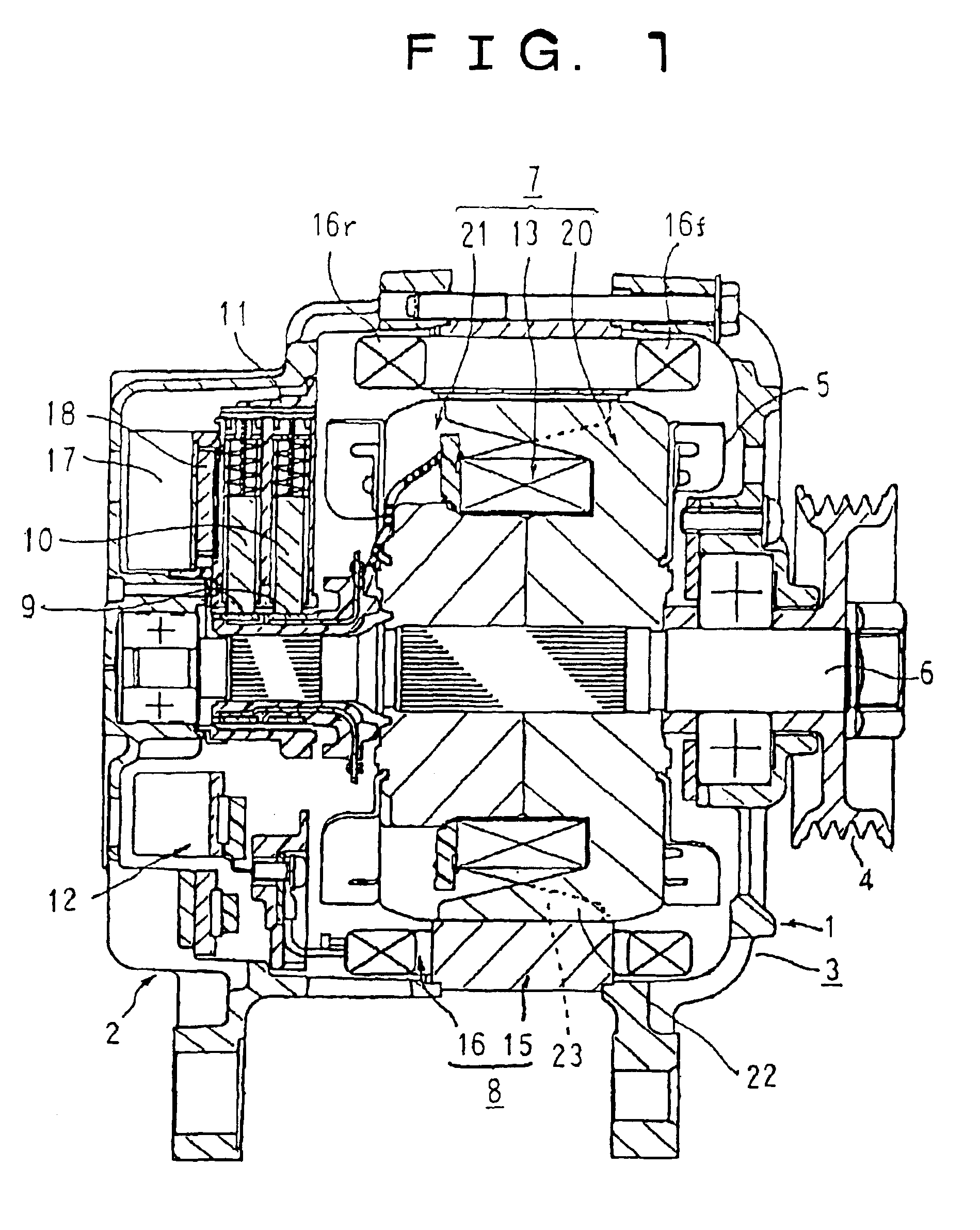
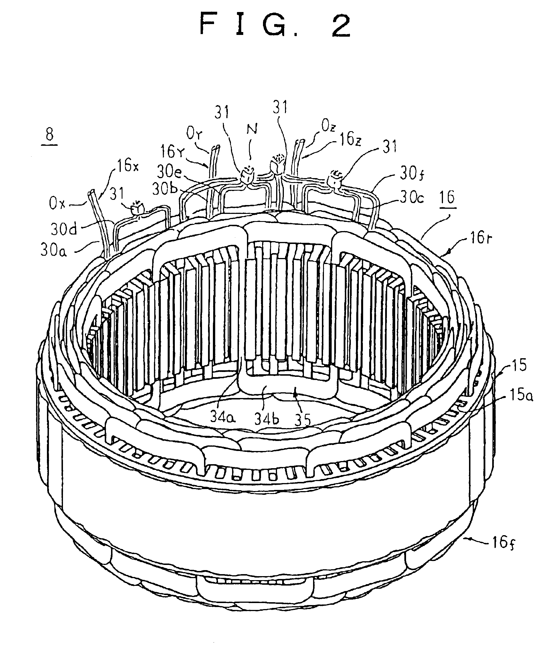
[0045]FIG. 1 is a longitudinal section showing an automotive alternating-current dynamoelectric machine according to Embodiment 1 of the present invention, FIG. 2 is a perspective showing a stator used in the automotive alternating-current dynamoelectric machine according to Embodiment 1 of the present invention, FIG. 3 is an end elevation showing part of a stator core used in the automotive alternating-current dynamoelectric machine according to Embodiment 1 of the present invention, and FIG. 4 is a circuit diagram showing an electrical circuit in the automotive alternating-current dynamoelectric machine according to Embodiment 1 of the present invention.

[0046]In FIG. 1, an automotive alternating-current dynamoelectric machine is provided with: a case 3 constituted by a front bracket 1 and a rear bracket 2 made of aluminum; a shaft 6 disposed inside the case 3, a pulley 4 secured to a first end portion of the shaft 6; a Lundell-type rotor 7 secured to the shaft 6; fans 5 secured to...

embodiment 2

[0083]FIG. 8 is a perspective showing a stator of an automotive alternating-current dynamoelectric machine according to Embodiment 2 of the present invention, FIG. 9 is a rear end elevation explaining installation of a single winding phase sub-portion constituting a stator winding of the automotive alternating-current dynamoelectric machine according to Embodiment 2 of the present invention, FIGS. 10 and 11 are both partial perspectives explaining a construction of the single winding phase sub-portion in the stator winding of the automotive alternating-current dynamoelectric machine according to Embodiment 2 of the present invention, and FIG. 12 is a rear end elevation explaining connections in the stator winding in the stator of the automotive alternating-current dynamoelectric machine according to Embodiment 2 of the present invention.

[0084]Moreover, in FIG. 9, solid lines indicate rear-end wiring, broken lines indicate front-end wiring, and black circles indicate joint portions.

[...

embodiment 3

[0110]FIG. 15 is a perspective showing a stator of an automotive alternating-current dynamoelectric machine according to Embodiment 3 of the present invention, and FIG. 16 is a rear end elevation explaining installation of a single winding phase sub-portion constituting a stator winding of the automotive alternating-current dynamoelectric machine according to Embodiment 3 of the present invention. Moreover, in FIG. 16, solid lines indicate rear-end wiring, broken lines indicate front-end wiring, and black circles indicate joint portions. Slots 41a are formed in the stator core 41 at a ratio of two slots per phase per pole at a nonuniform pitch alternating between an electrical angle of 32.5 degrees and an electrical angle of 27.5 degrees.

[0111]A construction of a single winding phase sub-portion constituting a stator winding 54 according to Embodiment 3 will be explained with reference to FIG. 16.

[0112]An a-phase winding phase sub-portion 54a is constituted by first to sixth wave wi...


PUM


Abstract

Slots are formed at a nonuniform pitch at a ratio of two slots per phase per pole. An X-phase winding phase portion constituting a stator winding is constructed by connecting in series an a-phase winding phase sub-portion and a d-phase winding phase sub-portion having a phase difference corresponding to an electrical angle of 34 degrees, a Y-phase winding phase portion is constructed by connecting in series a b-phase winding phase sub-portion and an e-phase winding phase sub-portion having a phase difference corresponding to an electrical angle of 34 degrees, and a Z-phase winding phase portion is constructed by connecting in series a c-phase winding phase sub-portion and an f-phase winding phase sub-portion having a phase difference corresponding to an electrical angle of 34 degrees.

Description

BACKGROUND OF THE INVENTION[0001]1. Field of the Invention[0002]The present invention relates to an automotive alternating-current dynamoelectric machine to which is mounted a stator provided with: a stator core in which slots are formed at a nonuniform pitch at a ratio of two slots per phase per pole; and a three-phase stator winding in which winding phase portions are each formed by zigzag-connecting first and second stator winding phase sub-portions installed in adjacent slot groups.[0003]2. Description of the Related Art[0004]In recent years, improvements in power output are being demanded of automotive alternating-current dynamoelectric machines due to increases in automotive vehicle loads while on the other hand, automotive vehicle engine compartments are becoming increasingly smaller, leaving little mounting space to spare.[0005]In Japanese Patent Laid-Open No. 2002-169490 (Gazette), an automotive alternating-current dynamoelectric machine is disclosed which achieves compactn...

Claims


Application Information

Patent Timeline
Patent Type & Authority Patents(United States)
IPC IPC(8): H02K3/04H02K3/28H02K19/22
CPCH02K3/28H02K3/12
Inventor KOMETANI, HARUYUKIASAO, YOSHIHITO
Owner MITSUBISHI ELECTRIC CORP
Why Eureka
Try Eureka