
Nondestructive, electrical impedance-based, thermal barrier coating inspection

a thermal barrier and inspection technology, applied in the direction of resistance/reactance/impedence, instruments, measurement devices, etc., can solve the problems of high operating temperature, high cost, and high cost of coatings, and achieve the effect of avoiding separation/delamination, avoiding potential defects, and avoiding tgo to bondcoat interface separation

Inactive Publication Date: 2005-12-27
RAYTHEON TECH CORP
View PDF9 Cites 35 Cited by
  • Summary
  • Abstract
  • Description
  • Claims
  • Application Information

AI Technical Summary

Benefits of technology

[0012]The current may pass through an electrolyte wetting the airfoil. The method may determine thicknesses of one or more layers of the coating and may identify or characterize voids within the coating or between the su

Problems solved by technology

Desired operating temperatures often exceed that possible for the alloys alone.
The coatings are subject to potential defects.
For example, the TGO to bondcoat interface tends to suffer from separations / delaminations.
Such defects tend to be inherent, so threshold degrees of defect may determine the utility of a given component.
Defects may also form during use.
Much of existing inspection involves destructive testing used to approve or reject batches of components.
Destructive testing suffers from many general drawbacks as do its various particular techniques.
The former includes the cost of destroyed components, the inaccuracy inherent in batch sampling, and the cost of time.
This may slightly reduce the time spent, but does not address the fundamental problems of destructive testing.

Method used


Image

  • Nondestructive, electrical impedance-based, thermal barrier coating inspection
  • Nondestructive, electrical impedance-based, thermal barrier coating inspection
  • Nondestructive, electrical impedance-based, thermal barrier coating inspection

Examples


Embodiment Construction

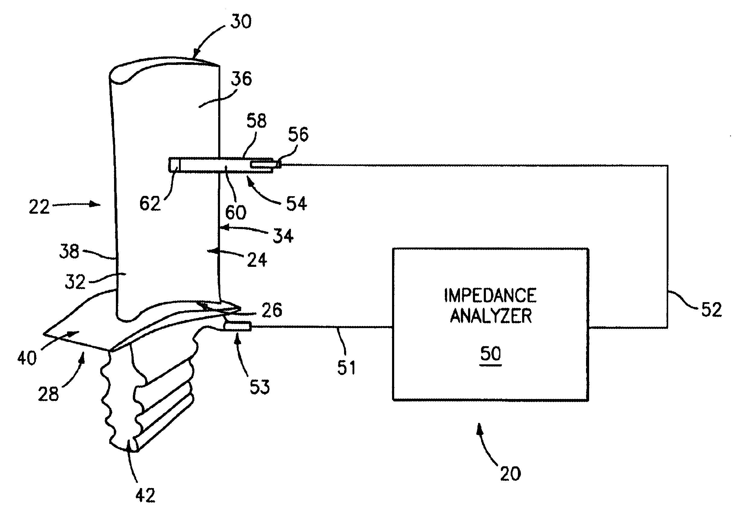
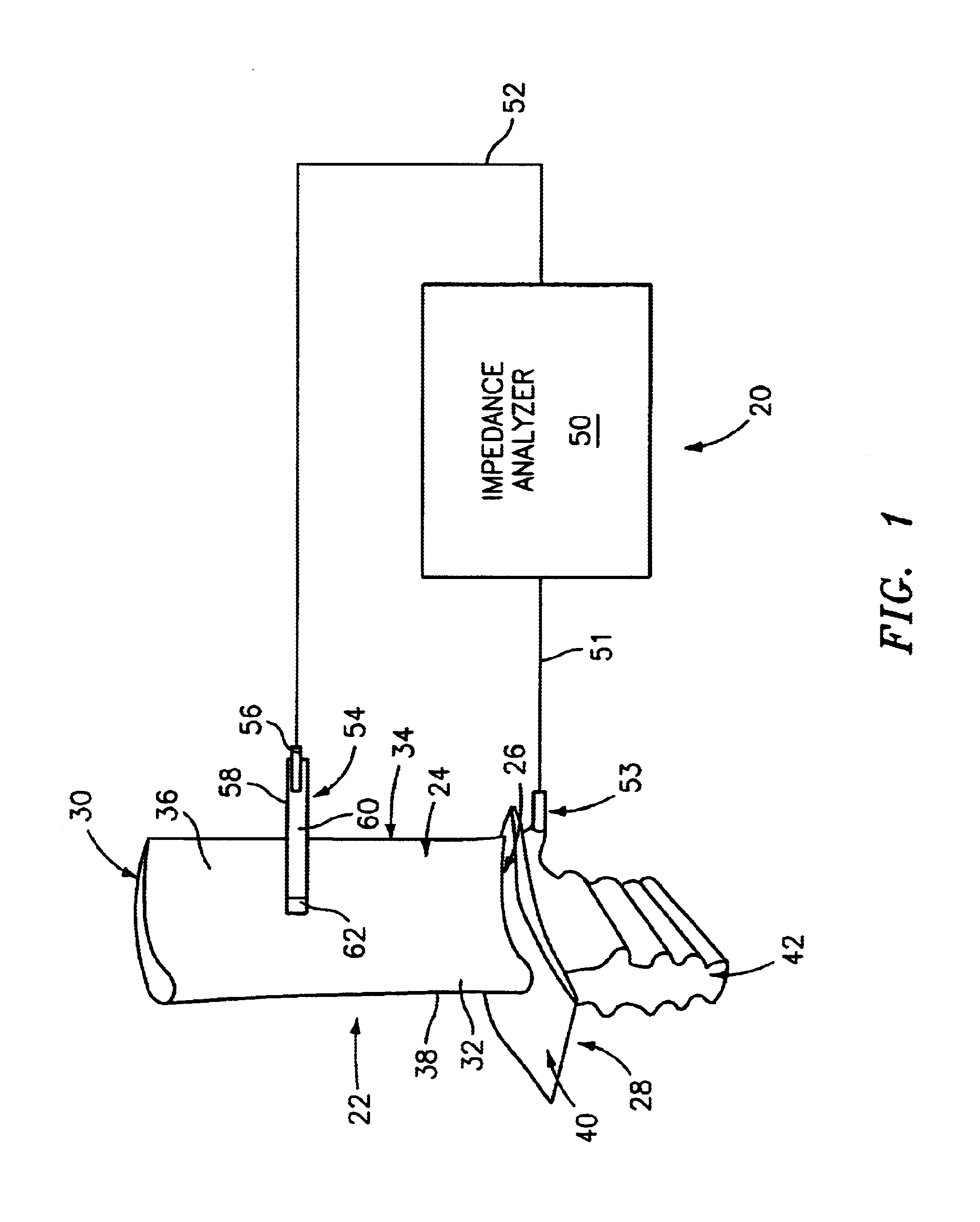
[0021]FIG. 1 shows an apparatus 20 for testing / inspecting a coated item such as a turbine element (e.g., a turbine engine blade 22). The exemplary blade 22 includes an airfoil 24 extending from a root 26 at a platform 28 to a tip 30. The airfoil has leading and trailing edges 32 and 34 separating pressure and suction sides 36 and 38. The platform has an outboard portion 40 for forming an inboard boundary / wall of a core flowpath through the turbine engine. A mounting portion or blade root 42 depends centrally from the underside of the platform 40 for fixing the blade in a disk of the turbine engine. In an exemplary embodiment, the portion 40 and airfoil 24 are coated.

[0022]The exemplary system 20 includes an impedance analyzer 50 coupled by conductors 51 and 52 to a pair of electrodes 53 and 54. The first electrode 53 may be a standard reference electrode contacted with an uncoated portion of the platform. The second electrode 54 is contacted with a coated portion of the blade and, t...


PUM


Abstract

A method and apparatus are provided for inspecting a coated substrate such as a multi-layer coating on a substrate of a turbine airfoil. At each of a number of locations along the airfoil a number of frequencies of alternating current are passed through the airfoil. At least one impedance parameter is measured. The measured impedance parameters are utilized to determine a condition of the coating.

Description

BACKGROUND OF THE INVENTION[0001](1) Field of the Invention[0002]This invention relates to inspection of thermal barrier coatings, and more particularly to inspection of coatings on turbine components.[0003](2) Description of the Related Art[0004]Gas turbine engine components (e.g., blades, vanes, seals, combustor panels, and the like) are commonly formed of nickel- or cobalt-based superalloys. Desired operating temperatures often exceed that possible for the alloys alone. Thermal barrier coatings (TBCs) are in common use on such components to permit use at elevated temperatures. Various coating compositions (e.g., ceramics) and various coating methods (e.g., electron beam physical vapor deposition (EBPVD) and plasma spray deposition) are known.[0005]An exemplary modern coating system is applied to the superalloy substrate by an EB-PVD technique. An exemplary coating system includes a metallic bondcoat layer (e.g., an overlay of NiCoCrAlY alloy or diffusion aluminide) atop the subst...

Claims


Application Information

Patent Timeline
IPC IPC(8): G01N27/82
CPCG01N27/82
Inventor BURNS, STEVEN M.BOSE, SUDHANGSHU
Owner RAYTHEON TECH CORP
Learn More