Image display apparatus and method

a technology of image display and image contour, applied in the field of image display apparatus and method, can solve the problems of reducing the effect of improving the blurring of moving images, generating flickers, and impairing the inherent, so as to achieve the effect of high-quality image display apparatus, and reducing image contour blurring

Inactive Publication Date: 2005-12-27
PANASONIC CORP
View PDF22 Cites 36 Cited by
  • Summary
  • Abstract
  • Description
  • Claims
  • Application Information

AI Technical Summary

Benefits of technology

[0123]As described above, in the thirty-sixth aspect, by use of a DMD display as the passive light modulation device, a high-quality image displ

Problems solved by technology

However, in the conventional apparatus, flicker is generated because the backlight blinks at a frequency of 60 Hz in synchronization with the vertical synchronizing signal.
This disadvantageously impairs the inherent advantage of liquid crystal displays that little flicker is generated and thus the viewer feels less fatigued when gazing at display details such as text charact

Method used


Image

  • Image display apparatus and method
  • Image display apparatus and method
  • Image display apparatus and method

Examples


first embodiment

(First Embodiment)

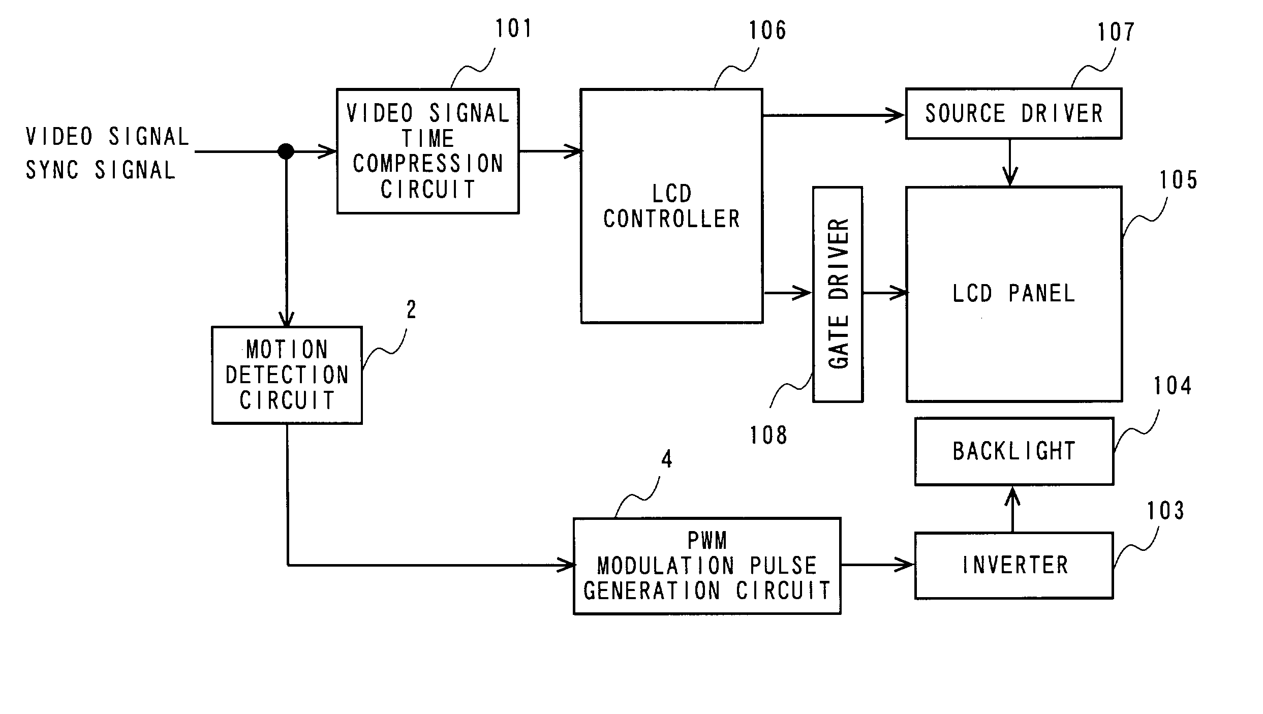
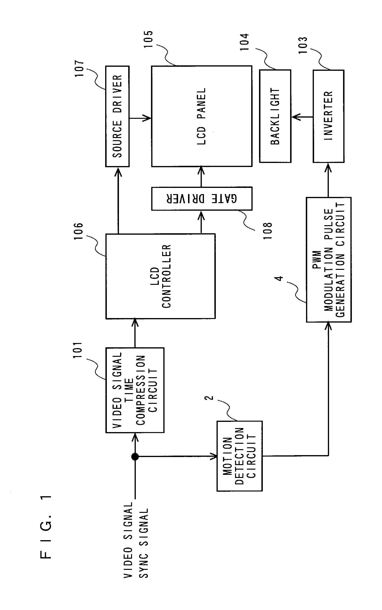
[0144]FIG. 1 illustrates a configuration of an image display apparatus of the first embodiment of the present invention. The image display apparatus includes a video signal time compression circuit 101, a motion detection circuit 2, a PWM modulation pulse generation circuit 4, an inverter 103, a backlight 104, a liquid crystal panel 105, an LCD controller 106, a source driver 107 and a gate driver 108. The same components as those of the conventional apparatus shown in FIG. 14 are denoted by the same reference numerals, and the detailed descriptions thereof are omitted here.

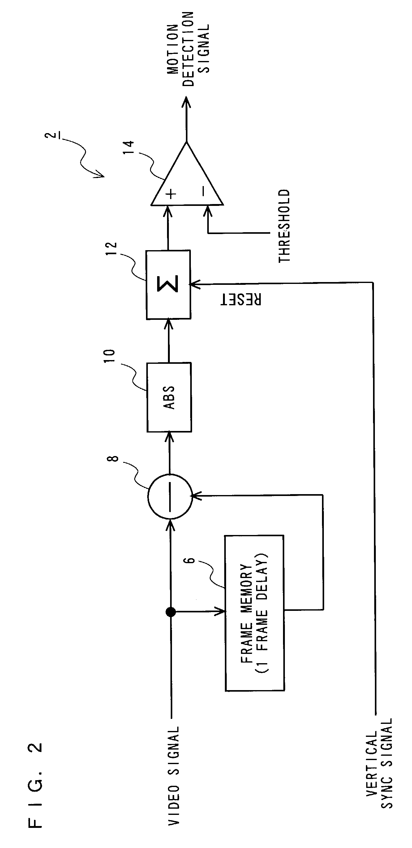
[0145]FIG. 2 illustrates a configuration of the motion detection circuit 2. A video signal and a synchronizing signal are supplied to the motion detection circuit 2. The motion detection circuit 2 includes: a frame memory 6 for delaying the video signal by one frame; a subtracter 8 for computing the one-frame difference from the video signal and the output of the frame memory 6; an absolute circ...

second embodiment

(Second Embodiment)

[0153]FIG. 5 illustrates a configuration of an image display apparatus of the second embodiment of the present invention. The image display apparatus includes a video signal time compression circuit 101, a motion detection circuit 22, a PWM modulation pulse generation circuit 24, an inverter 103, a backlight 104, a liquid crystal panel 105, an LCD controller 106, a source driver 107 and a gate driver 108. In FIG. 5, the same components as those of the conventional apparatus shown in FIG. 14 are denoted by the same reference numerals, and the descriptions thereof are omitted here.

[0154]FIG. 6 illustrates a configuration of the motion detection circuit 22. The motion detection circuit 22 receives a video signal and a synchronizing signal. The motion detection circuit 22 includes: a frame memory 6; a subtracter 8; an absolute circuit 10; a counter decoder 30 for outputting enable pulses ENABLE—a and ENABLE—b based on the synchronizing signal; an accumulator 26 for ac...

third embodiment

(Third Embodiment)

[0163]FIG. 10 illustrates a configuration of an image display apparatus of the third embodiment of the present invention. The image display apparatus includes: a gain control circuit 36 for controlling the gain of a video signal based on video signal gain control data; a video signal time compression circuit 101, a motion detection circuit 38 for outputting the video signal gain control data and modulation pulse width control data based on the video signal; a PWM modulation pulse generation circuit 40 for outputting a symptom pulse based on the modulation pulse width control data; an inverter 103: a backlight 104; a liquid crystal panel 105; an LCD controller 106; a source driver 107; and a gate driver 108. In FIG. 10, the same components as those of the conventional apparatus shown in FIG. 14 are denoted by the same reference numerals, and the descriptions thereof are omitted here.

[0164]FIG. 11 illustrates a configuration of the motion detection circuit 38. The vi...


PUM


Abstract

A liquid crystal display apparatus that uses a backlight for display includes a video signal time compression circuit for compressing a video signal in the time axis direction and outputting the time-compressed video signal, an LCD controller for driving a liquid crystal panel based on the time-compressed video signal, and a source driver and a gate driver. The liquid crystal display apparatus also includes a motion detection circuit for detecting the amount of motion of a display image based on the video signal, a PWM modulation pulse generation circuit for generating modulation pulses different in frequency according to the detection result from the motion detection circuit, and an inverter for lighting up the backlight based on the modulation pulses, to thereby enable reduction of image contour blurring in a moving image and reduction of flicker in a still image.

Description

TECHNICAL FIELD[0001]The present invention relates to an image display apparatus and method. More particularly, the present invention relates to an image display apparatus and method for displaying an image by driving a passive light modulation device, which modulates light from a light source in a pixel-by-pixel manner based on an electric signal, based on a video signal compressed in the time axis direction.BACKGROUND ART[0002]In CRTs used for image display apparatuses, an electron beam strikes a phosphor surface to cause light emission. When measured for a miniscule period of time, each point of the screen is displayed only for an extremely short time by persistence of the phosphor. In CRTs, this point emission is sequentially scanned, to display an image of one frame using the persistence of vision by the eyes. This type of display device is called an impulse type display device.[0003]In liquid crystal displays, a light modulation device generally called a hold type display devi...

Claims


Application Information

Patent Timeline
IPC IPC(8): G02F1/133G02F1/13357G09G3/20G09G3/34G09G3/36
CPCG09G3/3406G09G3/36G09G2310/08G09G2320/0247G09G2320/0261G09G2320/062G09G2320/0626G09G2320/064G09G2320/0646G09G2320/0653G09G2320/066G09G2320/103G09G2320/106
Inventor FUNAMOTO, TAROMACHIDORI, WATARUARIMOTO, KATSUYUKIOHTA, YOSHIHITOKOBAYASHI, TAKAHIROKUMAMOTO, YASUHIROKARIYA, TETSUO
Owner PANASONIC CORP
Why Eureka
Try Eureka