
Condensation particle counter

a technology of condensation and particle counter, which is applied in the field of condensation, can solve the problems of insufficient use of technology at present, inability to continuously measure particles, inaccurate measurement of particle number, etc., and achieve the effect of quick and easy counting of ultra-fine particles floating in air

Inactive Publication Date: 2005-12-27
HYUNDAI CALIBRATION & CERTIFICATION TECH CO LTD
View PDF10 Cites 26 Cited by
  • Summary
  • Abstract
  • Description
  • Claims
  • Application Information

AI Technical Summary

Benefits of technology

"The present invention provides a condensation particle counter that can quickly and easily count ultra-fine particles in air. It can use different operating liquids and is suitable for use in semiconductor clean rooms. The counter has a high flow rate and is designed to measure the number of particles accurately. It consists of a storage pool with an operating liquid, a saturator, a heater, a capillary, an optical instrument, and a suction means."

Problems solved by technology

However, since the measurement of the particles according to a conventional condensation particle counter in which the particles grow by such an expansion process should be intermittently made, there is a problem in that continuous measurement of the particles is greatly restricted.
Accordingly, this technology has been hardly employed at present.
However, very high supersaturation may be formed partly in the mixing type condensation particle counter, and thus, the vapor is spontaneously condensed into the water droplets even though the particles used for the condensation nuclei are not provided therein.
Therefore, there is also a problem in that the measurement of the number of the particles is inaccurate.
In case of the third type or conductive cooling type condensation particle counter, the thermo-electric cooler used for keeping the condenser at the low temperature of 10° C. is poor in view of a coefficient of performance for removing heat from the condenser by using electricity, and thus, the cooler is good for removing a small quantity of heat from the condenser but inappropriate for removing a large quantity of heat from the condenser.
Accordingly, a capacity of the condensation particle counter used commonly and currently is about 0.3 to 1.0 liter / min since it is difficult to cool down a large quantity of air.
In particular, in case of the semiconductor clean rooms where it is necessary to sample the particles at a high flow rate, a need for a condensation particle counter capable of sampling the particles at the high flow rate has been required for a long time.
However, suitable equipment has not yet been developed.
Thus, there is a problem in that the ultra-fine particles cannot be measured through the optical instrument.
That is, the conductive cooling type condensation particle counter has a disadvantage in that only the alcohol must be utilized as the operating liquid.
In particular, since the alcohol becomes a pollution source, the conductive cooling type condensation particle counter in which the alcohol should be used as the operating liquid is not suitable for a semiconductor fabrication process.

Method used


Image

  • Condensation particle counter
  • Condensation particle counter
  • Condensation particle counter

Examples


Embodiment Construction

[0014]Hereinafter, a preferred embodiment of a condensation particle counter according to the present invention will be explained in detail with reference to the accompanying drawings.

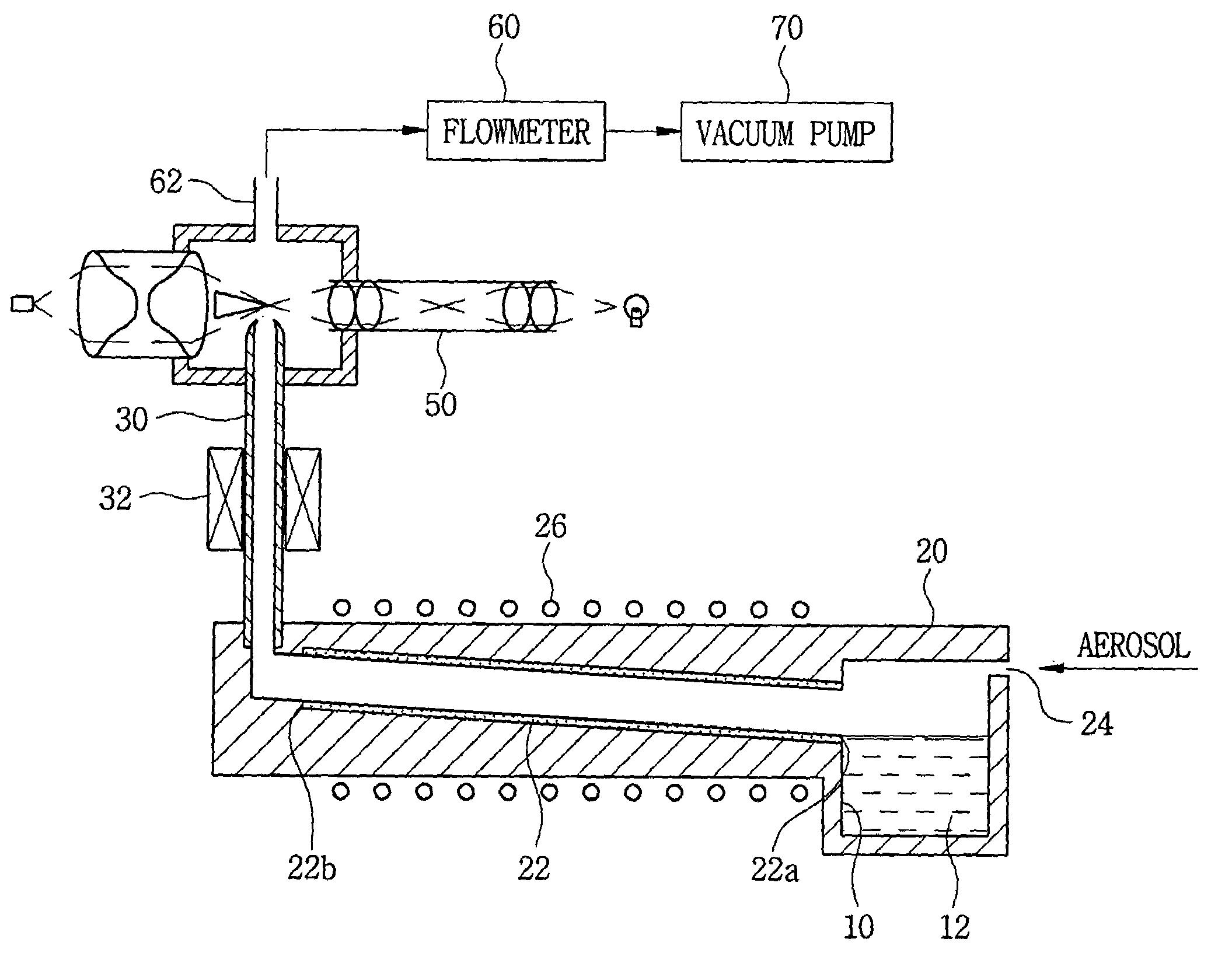
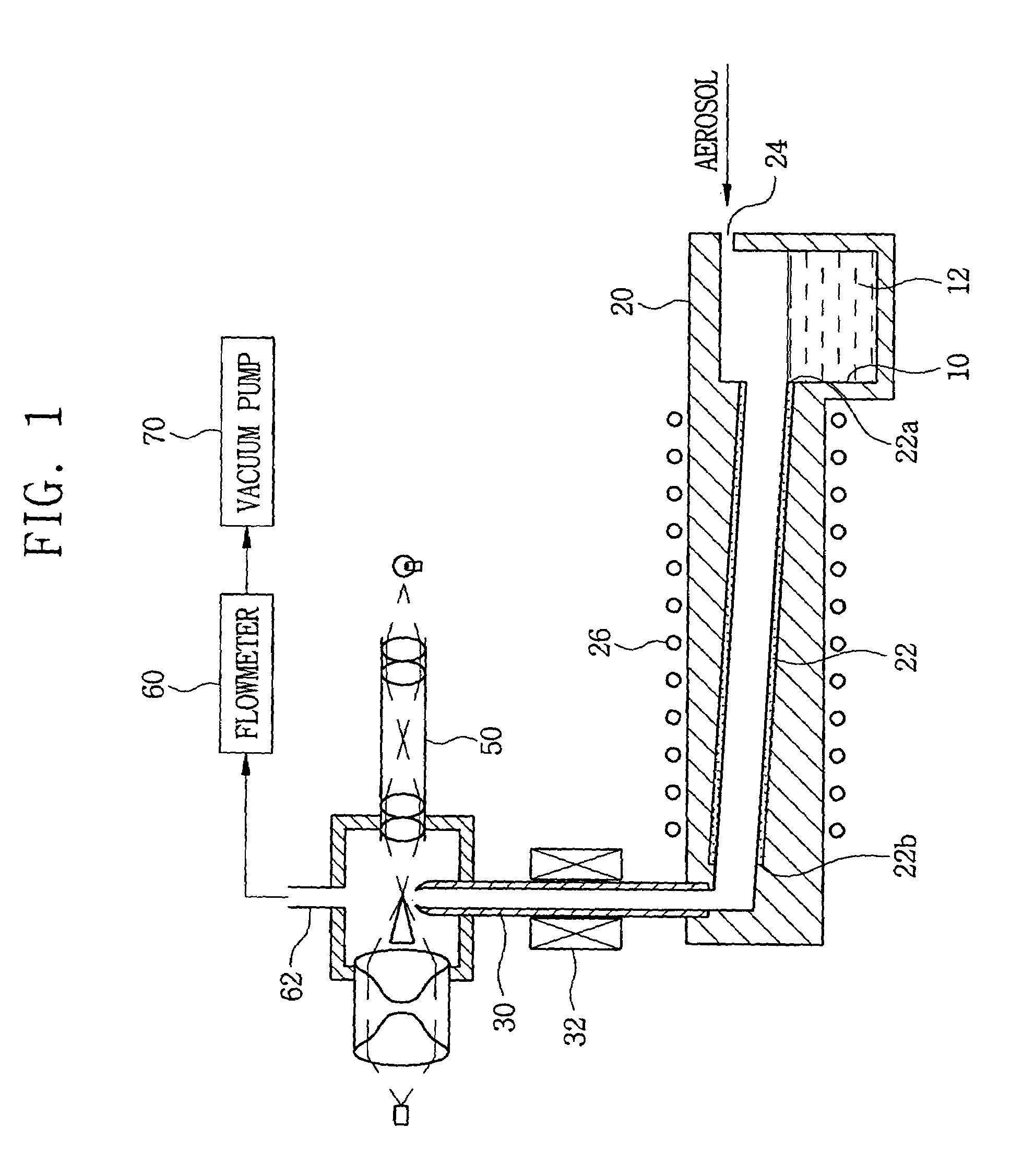
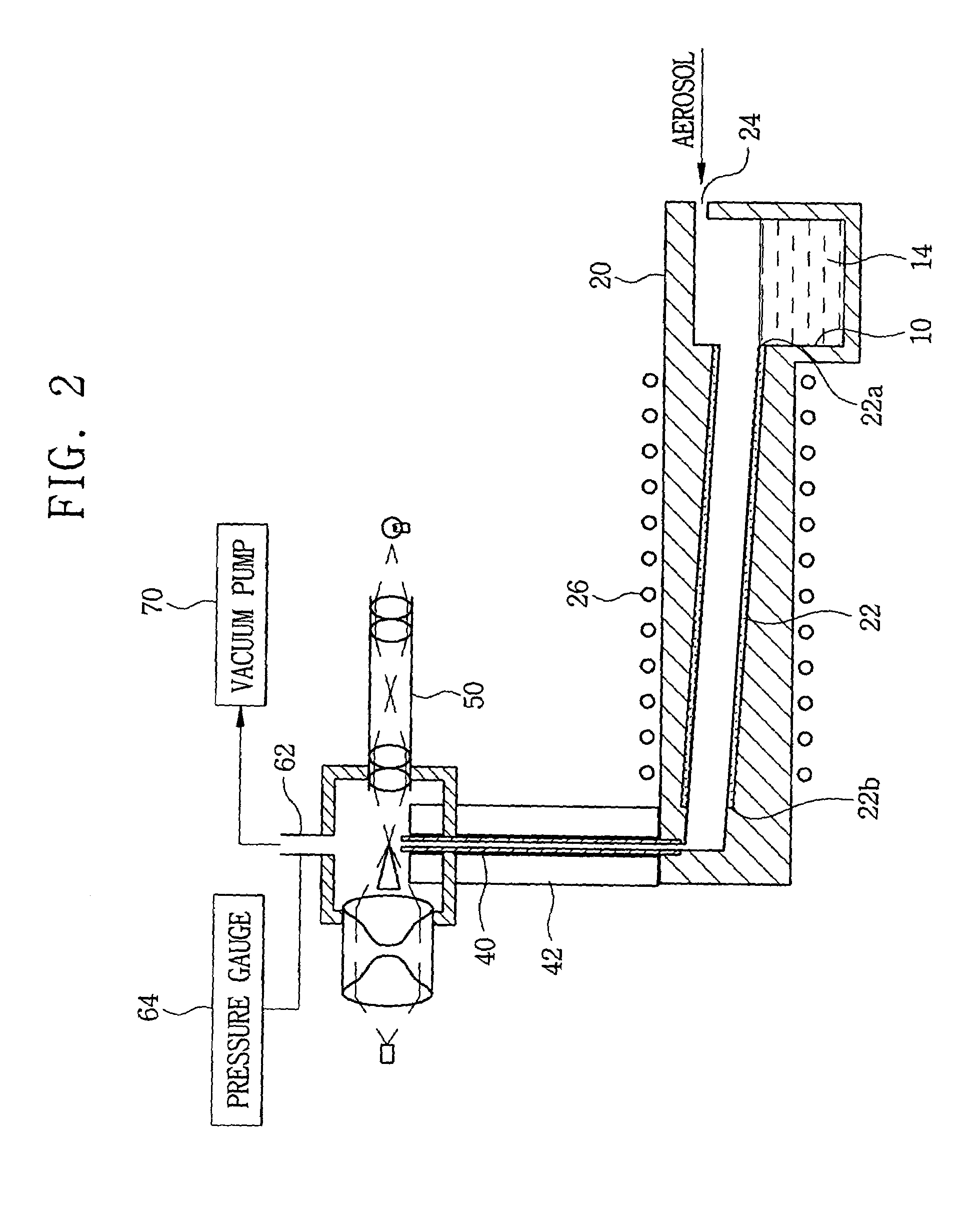
[0015]FIG. 2 is a sectional view showing the constitution of the condensation particle counter according to the present invention. In FIG. 2, like elements, which are the same as those of the conventional condensation particle counter shown in FIG. 1, are denoted by like reference numerals.

[0016]An operating liquid 14 is contained in a storage pool 10, and a cylindrical absorbing member 22 is attached to an inner wall of a saturator 20 integrally formed with the storage pool 10. In the present invention, various liquids including alcohol and water can be utilized as the operating liquid. The operating liquid is absorbed into the absorbing member 22 which is made of porous material such as nonwoven fabric and of which one end 22a is immersed into the operating liquid within the storage pool 10, and thus...


PUM

PropertyMeasurementUnit
pressureaaaaaaaaaa
sizesaaaaaaaaaa
particle sizeaaaaaaaaaa

Abstract

A condensation particle counter measures the number of ultra-fine particles by growing the ultra-fine particles through a condensing process. The counter includes a capillary in which vapor of operating liquid is condensed and the ultra-fine particles grow. An insulating material surrounds the capillary to shut out heat flow between the capillary and the environment. The condensation particle counter can use various operating liquids including alcohol and water, and can be also applied to semiconductor clean rooms.

Description

TECHNICAL FIELD[0001]The present invention relates to a particle counter, and more particularly, to a condensation particle counter which measures the number of ultra-fine particles by growing the ultra-fine particles having their sizes of 0.1 μm or less which are used as condensation nuclei.BACKGROUND ART[0002]Measurement of the number of ultra-fine particles is prerequisite to fundamental study of the particles for air pollution measurement, and has also been applied to investigation of the cause why the ultra-fine particles have been generated in semiconductor clean rooms and the like so that the clean rooms can be kept at a clean state by removing the ultra-fine particles from the clean rooms. As well known in the art, an optical instrument such as a laser is utilized to measure the number of the ultra-fine particles. In general, a particle measurement limit of the optical instrument corresponds to about 0.1 μm in particle size. Thus, a condensation particle counter has been uti...

Claims


Application Information

Patent Timeline
Patent Type & Authority Patents(United States)
IPC IPC(8): H01L21/02G01N15/00G01N15/06G01N15/14
CPCG01N15/065G01N15/14G01N2015/0049G01N2015/0681H01L21/02
Inventor AHN, KANG-HOKIM, SANG-SOOJEONG, HAE-YOUNG
Owner HYUNDAI CALIBRATION & CERTIFICATION TECH CO LTD
Learn More