Apparatus for information recording and reproducing

a technology for information recording and reproducing, applied in the field of digital data recording and reproducing apparatus, can solve the problems of further degradation of the quality of the input signal to the phase error detector, further degradation of the control signal, and further degradation of the signal quality, so as to reduce the data error rate

Inactive Publication Date: 2005-12-27
HITACHI VIDEO & INFORMATION SYST +1
View PDF6 Cites 15 Cited by
  • Summary
  • Abstract
  • Description
  • Claims
  • Application Information

AI Technical Summary

Benefits of technology

[0016]As a countermeasure against the above problem, each of JP-A-10-293973 and JP-A-9-17130 discloses that the output of Viterbi detecting circuit for data regeneration is used as a reference signal for phase comparison. This can sufficiently lower a probability of detection error occurrence to allow the phase error to be accurately detected.
[0018]Accordingly, it is an object of the present invention to provide a signal processing circuit which can reduce the data error rate therein by using the Viterbi algorithm being adopted.

Problems solved by technology

However, even with the phase error detector provided with a high performance, there still remains following problem.
Namely, when degradation of the signal recorded on a recording medium, increase in noise in a signal processing circuit, and an error in parameter setting in the signal processing circuit cause considerable degradation in quality of the signal inputted to the phase error detector, temporary quality degradation in a control signal causes further degradation in quality of the input signal to the phase error detector.
This will sometimes induce continuous detection error that leads to further degradation in the control signal.
Occurrence of such a phenomenon increases a bit error rate of a signal at the output of the signal processing circuit thereby to degrade the performance of the whole system.

Method used


Image

  • Apparatus for information recording and reproducing
  • Apparatus for information recording and reproducing
  • Apparatus for information recording and reproducing

Examples


first embodiment

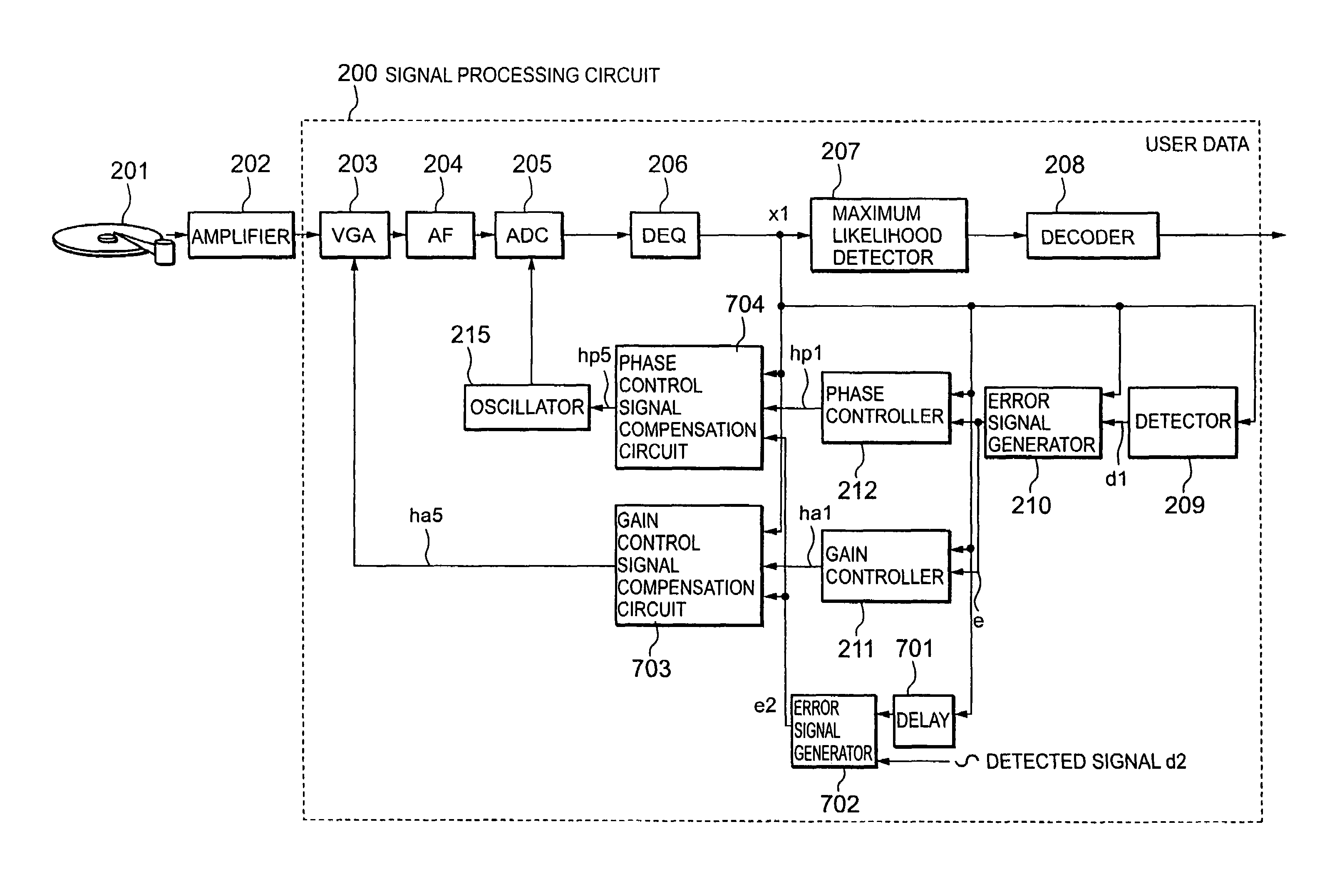
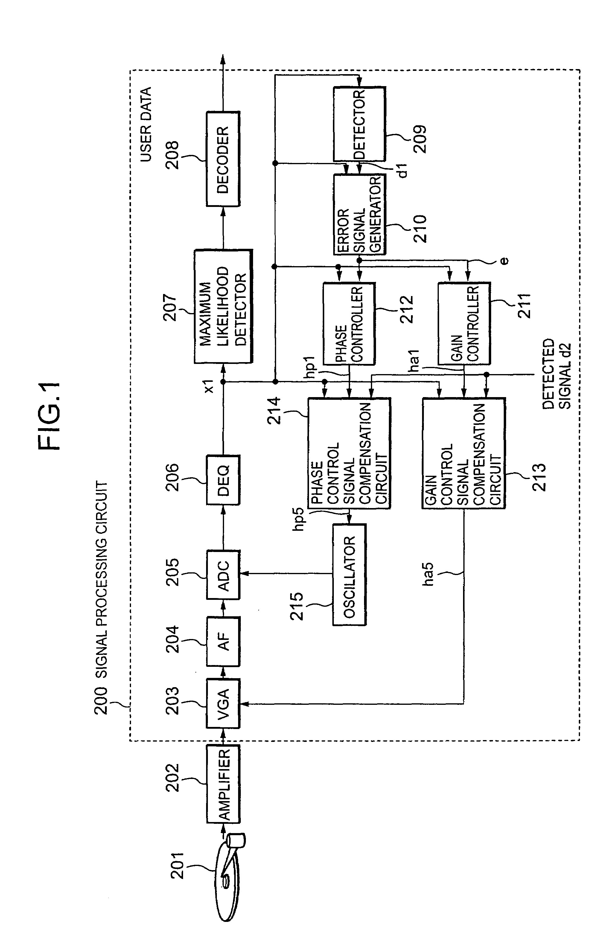
[0046]FIG. 1 is a block diagram showing a configuration of a magnetic disk drive including a phase control circuit and a gain control circuit in the present invention.

[0047]Digital data written to a recording medium is read out by a head 201 and amplified by an amplifier 202. The amplified signal is then inputted to a signal processing circuit 200.

[0048]The signal inputted to the signal processing circuit 200 is adjusted to have an appropriate amplitude by a variable-gain-amplifier (VGA) 203 and sent to an analog filter (AF) 204. The AF 204 removes from an output of the VGA 203 higher frequency components, which will become noises when a sampling of the output is carried out in a ADC 205, and along with this, carries out waveform shaping of the output.

[0049]A signal outputted from the AF 204 is converted to a digital signal by the A / D converter (ADC) 205. The digital signal is then inputted to a digital equalizer (DEQ) 206 to be subjected to wave form equalization. When the wave for...

second embodiment

[0095]In the next, the present invention will be explained.

[0096]FIG. 12 is a block diagram schematically showing a configuration of a data regenerating circuit 1039 as the second embodiment. The data regenerating circuit 1039 corresponds to the signal processing circuit 200 in the first embodiment. In the data regenerating circuit 1039, there is carried out the data regeneration by PRML. In the data generating circuit 1039, the variable-gain-amplifier (VGA) 203, the analog filter (LPF) 204, the analog to digital converter (ADC) 205, and the digital equalizer (EQ) 206 are the same as those in the first embodiment. A Viterbi decoding circuit (ML) 1035 corresponds to the maximum likelihood detector 207 and the decoder 208 in the signal processing circuit 200 in the first embodiment, and carries out data regeneration by the Viterbi algorithm about a signal outputted from the equalizer 206 to decode the signal into binary data. At the same time, the output of the equalizer 206 is also s...


PUM

PropertyMeasurementUnit
phase erroraaaaaaaaaa
phase compensatingaaaaaaaaaa
compensated phase erroraaaaaaaaaa

Abstract

In order to generate a sampling clock having a higher accuracy, a synchronous signal generating circuit is provided with a phase error detector, detecting a phase error of a read out signal digitized on the basis of FDTS algorithm, and a VCO, controlling an oscillation frequency on the basis of a phase error detected by the phase error detector, to generate a synchronous signal by the VCO. On the basis of the synchronous signal generated by the synchronous signal generating circuit, an ADC digitizes the read out signal. The digitized read out signal is then converted to binary data by a detection circuit.

Description

CROSS-REFERENCE TO RELATED APPLICATIONS[0001]This is a Rule 53(b) Continuation of U.S. application Ser. No. 09 / 793,924 filed 28 Feb. 2001, now U.S. Pat. No. 6,791,776, the contents of which is incorporated herein by reference in its entirety.[0002]This application claims a priority based on Japanese Patent Application Nos. 2000-131523 and 2000-210687 filed on Apr. 26, 2000, and Jul. 6, 2000, respectively, the entire contents of which are incorporated herein by reference for all purposes.FIELD OF THE INVENTION[0003]The present invention relates to a digital data recording and reproducing apparatus, in particular, to a signal processing circuit which effectively carries out signal processing such as reading out from a recording medium by controlling a phase-locked loop circuit and a variable-gain-amplifier with a partial response maximum likelihood decoding (hereinafter abbreviated as PRML), and to a digital data regenerating apparatus using the signal processing circuit.BACKGROUND OF...

Claims


Application Information

Patent Timeline
Patent Type & Authority Patents(United States)
IPC IPC(8): G11B5/012G11B5/09G11B20/10G11B20/14
CPCG11B20/10009G11B20/1403G11B5/012G11B5/09
Inventor KATO, TAKATOSHINISHIYA, TAKUSHIYAMAKAWA, HIDEYUKINARA, TAKASHINAKAI, NOBUAKIIDE, HIROSHISUZUMURA, SHINTAROTAKASHI, TERUMI
Owner HITACHI VIDEO & INFORMATION SYST
Why Eureka
Try Eureka