
Air conditioning system

a technology of air conditioning system and air cycle machine, which is applied in the direction of steam/vapor condensers, lighting and heating apparatus, applications, etc., can solve the problems of inability to operate an air cycle machine purely due to the failure of these valves, and achieve high reliability, high cooling performance, and good redundancy

Inactive Publication Date: 2006-01-03
LIEBHERR AEROSPACE LINDENBERG
View PDF11 Cites 23 Cited by
  • Summary
  • Abstract
  • Description
  • Claims
  • Application Information

AI Technical Summary

Benefits of technology

[0029]It is thus the object of the present invention to improve an air conditioning system of the type mentioned in the introduction such that it comprises a small number of components, a compact design, a high degree of reliability, good redundancy, as well as a high cooling performance if one air cycle machine fails during flight.
[0035]In a preferred embodiment of the present invention, each of the two separate, i.e. fluidically separate, ram air outlet ducts is further divided into a fan outlet duct and a fan bypass duct. The ram air outlet ducts can either be mechanically divided (separate) or mechanically shared (parallel). The bypass duct is used to increase the throughput in the ram air duct during flight.
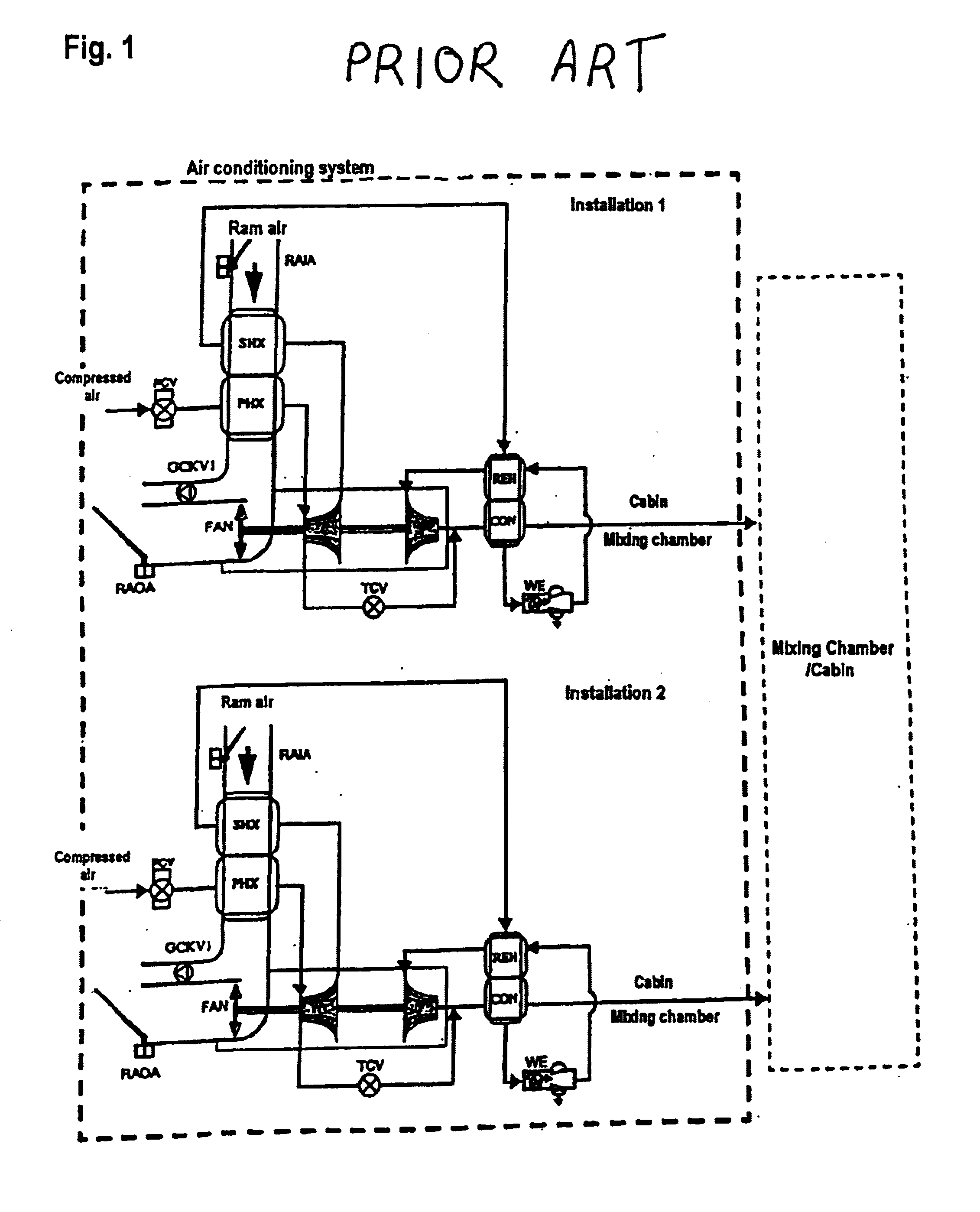
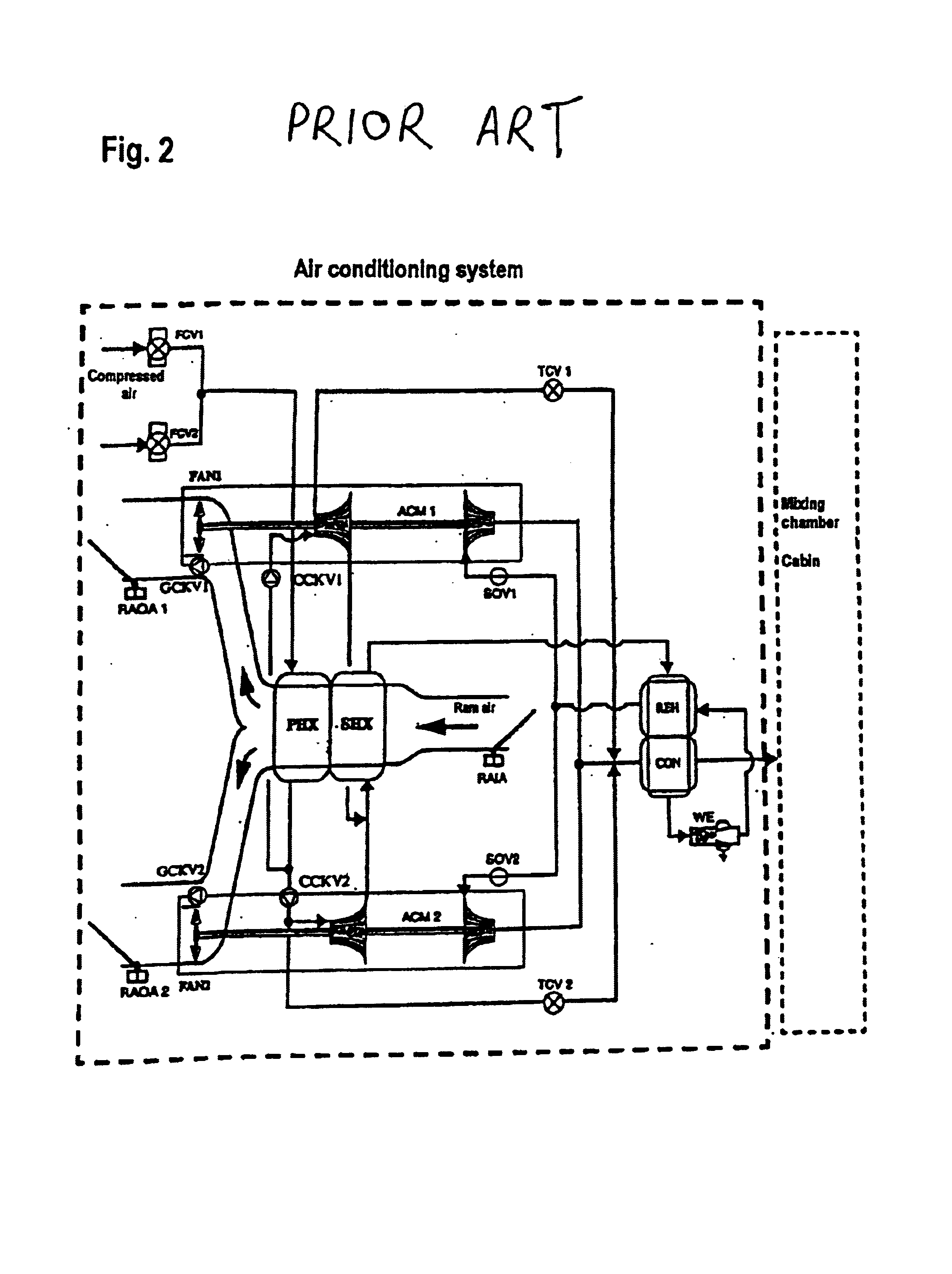
[0036]In each of the bypass ducts, a check valve and / or a shared or two separate ram air duct outlet flaps for closing off the bypass ducts of the ram air outlet ducts can be provided. Thus the outlet of the two bypass ducts can be closed by means of a shared flap or by means of two flaps of which one each is arranged for each bypass duct. In the closed state the flap or flaps close only the bypass ducts. In contrast to the state of the art according to FIG. 1 and FIG. 2, the present system can be operated with only one ram air duct outlet flap. This results in advantages relating to cost, space and weight.
[0042]At the ram air end, the primary and secondary heat exchangers can be arranged in series, in parallel, or in such a way that ambient air or ram air flows through part of the primary heat exchanger in parallel, while it flows in series to part of the secondary heat exchanger. In the first case, at the ram air end, the primary heat exchanger is arranged downstream of the secondary heat exchanger; while in the second case it is arranged in parallel, and in the third case it is arranged partially in series and partially parallel. The latter has the advantage in that the primary heat exchanger is at least partly, preferably at its outlet region at the compressed-air end, impinged with cool ambient air or ram air.

Problems solved by technology

As a result of this, failure of an air cycle machine purely due to failure of these valves is impossible.

Method used


Image

  • Air conditioning system
  • Air conditioning system
  • Air conditioning system

Examples


Embodiment Construction

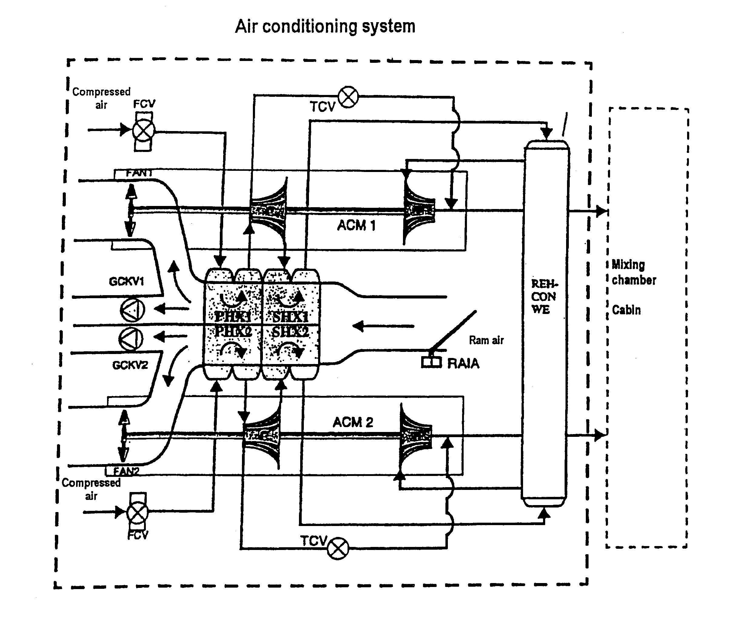
[0058]FIG. 3 is a diagrammatic view of one possible embodiment of the air conditioning system according to the present invention. A primary heat exchanger and a secondary heat exchanger are arranged in the ram air duct. Both heat exchangers comprise heat exchanger units PHX 1 and PHX 2, and SHX 1 and SHX 2 respectively, which units are separate from each other from the point of view of fluidics and heat technology. Units PHX 1 and PHX 2 as well as SHX 1 and SHX 2 can form a mechanical unit and can also be interconnected which results in a particularly compact design. It can be provided for the heat exchanger units PHX 1 and SHX 1 as well as PHX 2 and SHX 2 to be designed so as to be separated by a gap.

[0059]As shown in FIG. 3, a shared ram air inlet duct is provided for both heat exchanger units SHX 1 / PHX 1 and SHX 2 / PHX 2. The ram air flows through the heat exchanger unit SHX 1 and subsequently through the unit PHX 1 and, separated by it, through the heat exchanger units SHX 2 and ...


PUM


Abstract

The following invention relates to an air conditioning system, in particular for aircraft, comprising at least one heat exchanger, arranged in a ram air duct, for cooling compressed air by means of a fluid, and comprising at least a first and a second air cycle machine which at the compressed-air end are connected to the heat exchanger. A particularly compact, reliable, redundant and economical arrangement is achieved in that the heat exchanger comprises at least one first heat exchanger unit and a second heat exchanger unit, of which one each is connected at the compressed-air end to one of the air cycle machines, and in that ram air outlet ducts which are fluidically separate from each other are provided, of which one is connected to the first heat exchanger unit and another is connected to the second heat exchanger unit.

Description

BACKGROUND OF THE INVENTION[0001]The present invention relates to an air conditioning system, in particular for aircraft, comprising at least one heat exchanger, arranged in a ram air duct, for cooling compressed air by means of a fluid, and comprising at least a first and a second air cycle machine which at the compressed-air end are connected to the heat exchanger.[0002]Such air conditioning systems are used for air conditioning, i.e. heating and cooling, of the cabin, for cabin pressurisation as well as for fresh air supply. In particular in aircraft construction it is of special importance that the air conditioning system is small and lightweight as possible. Furthermore, it is essential that the above-mentioned functions of the air conditioning system are carried out both during normal operation and during partial failure of the installation (redundancy).[0003]From the state of the art, two different concepts for this are known, as shown below:[0004]FIG. 1 shows a first embodim...

Claims


Application Information

Patent Timeline
IPC IPC(8): F25D9/00B64D13/06F25B9/00
CPCB64D13/06F25B9/004B64D2013/0662
Inventor BRUTSCHER, NORBERTHAAS, JOACHIM
Owner LIEBHERR AEROSPACE LINDENBERG
Learn More