Sample analysis systems

a sample analysis and sample technology, applied in the field of sample analysis systems, can solve the problems of not being comprehensively screened, not being able to identify a few hundred targets, and being a manual and time-consuming process

Inactive Publication Date: 2006-01-03
MOLECULAR DEVICES
View PDF396 Cites 358 Cited by
  • Summary
  • Abstract
  • Description
  • Claims
  • Application Information

AI Technical Summary

Benefits of technology

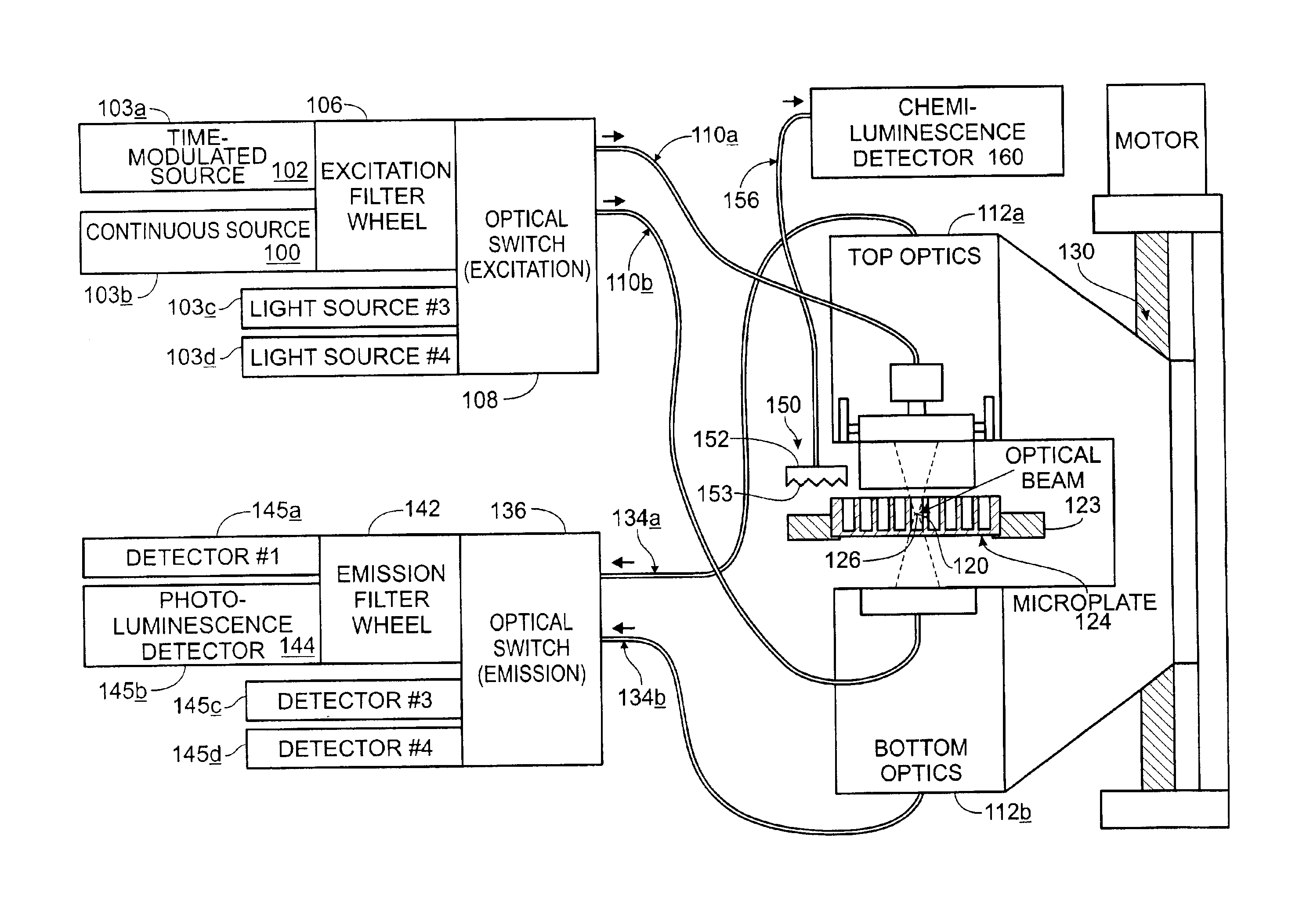
[0039]The invention provides systems, and components thereof, for analyzing samples. These systems include apparatus and methods for generating, transmitting, detecting, and/or analyzing light, including without limitation high-throughpu

Problems solved by technology

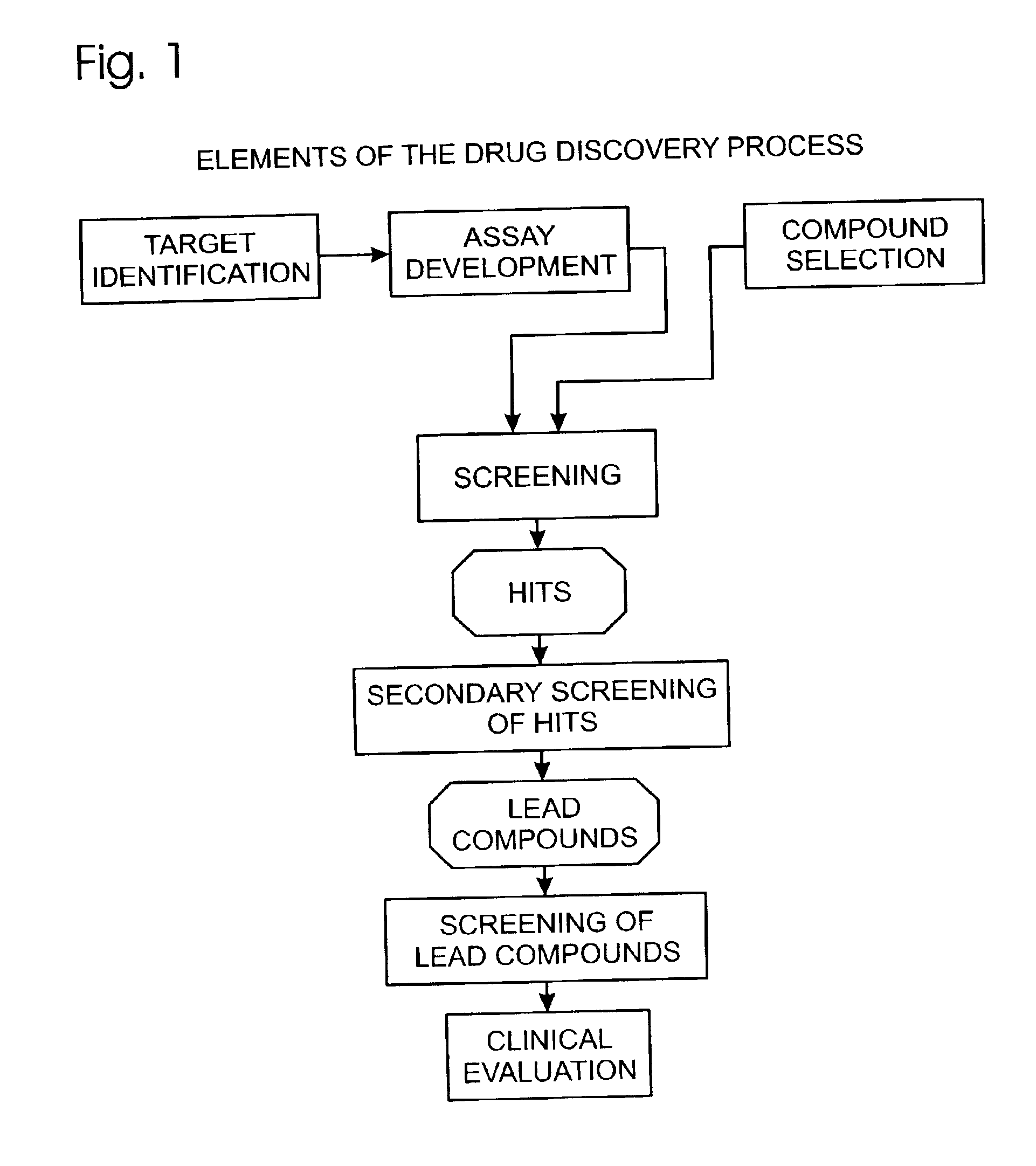
Until recently, scientists using conventional methods had identified only a few hundred targets, many of which have not been comprehensively screened.
Due to the recent dramatic increase in the number of available compounds and targets, a bottleneck has resulted at the screening stage of the drug discovery process.
Historically, screening has been a manual, time-consuming process.
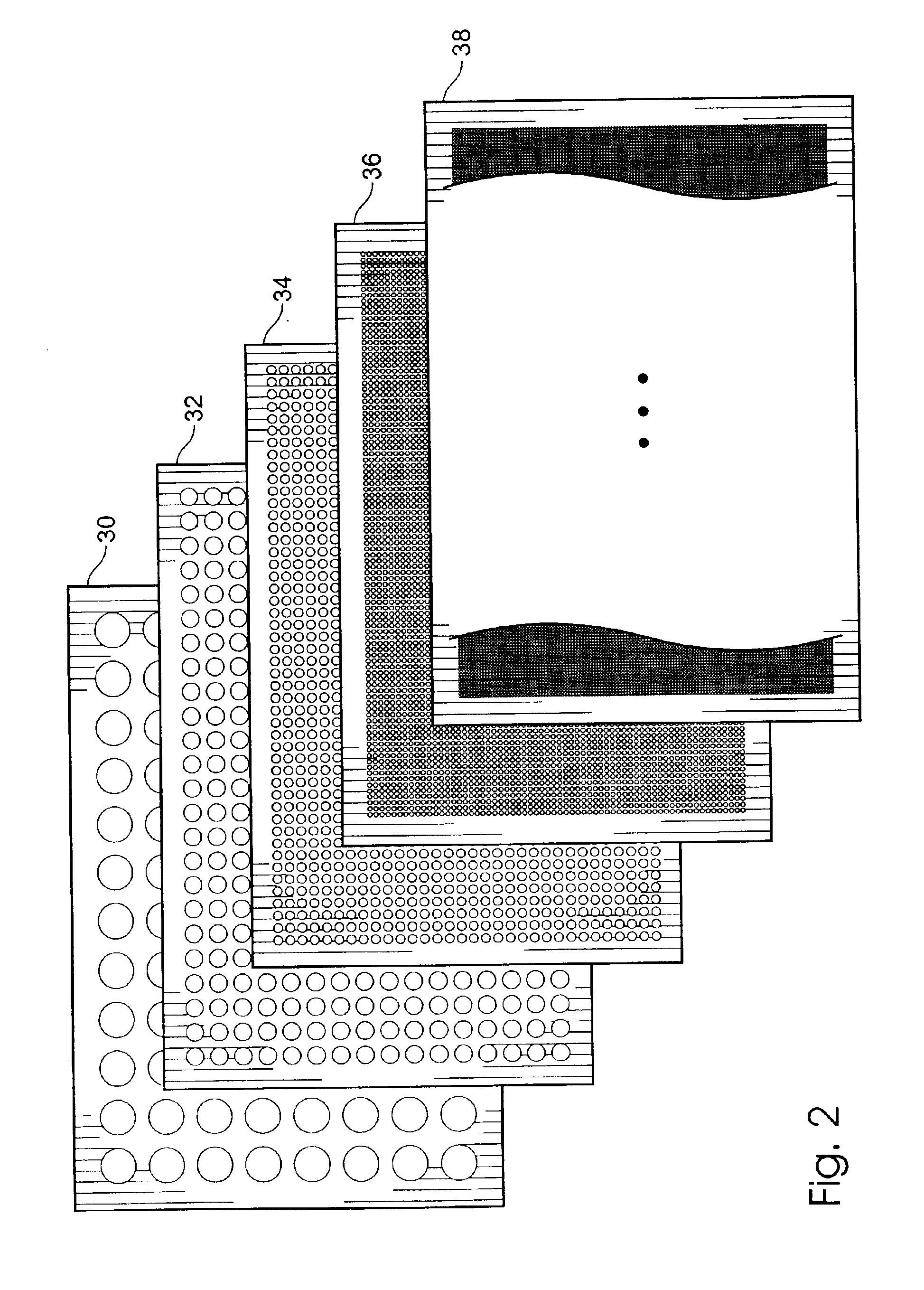
Many analyzers are not flexible enough to read microplates having different numbers of wells, such that it currently may be necessary to provide different analyzers for different modes of analysis.
Moreover, many analyzers are not sensitive or accurate enough to read results from the smaller wells associated with the higher-density microplates.
Inadequate sensitivity may result in missed hits, limited research capabilities, increased costs of compounds, assays, and reagents, and lower throughput.
Most analyzers in use today are not designed specifically for high-t

Method used


Image

  • Sample analysis systems
  • Sample analysis systems
  • Sample analysis systems

Examples


example 4

C.4 Example 4

[0546]FIG. 58 shows yet another alternative device constructed in accordance with aspects of the invention, using a Digital Mirror Device (DMD). This device has a large array of very small (10-20 micron), very fast mirrors that can be rotated under electronic control. Placed in an image plane, they can be used to control the area that is reflected into the optics. A suitable DMD (used for video projectors) may be obtained commercially from Texas Instruments Inc. (Dallas, Tex.).

example 5

C.5 Example 5

[0547]The following numbered paragraphs describe additional and / or alternative aspects of the invention:

[0548]1. An apparatus for detecting light transmitted from a substrate having a plurality of sample sites, the apparatus comprising (A) a stage for supporting the substrate, the stage being configured to move the substrate in a first direction so that the sample sites pass sequentially through an examination region delimited by a detection initiation position and a detection termination position; (B) a detector configured to detect light; (C) an optical relay structure configured to transmit light from a sensed volume within the examination region to the detector, the sensed volume being smaller than the examination region; and (D) an automated scanning mechanism configured to move the sensed volume in the first direction between the detection initiation position and the detection termination position; wherein the sensed volume tracks a first sample site as it moves b...

example 1

D.1 Example 1

[0602]To test this circuit, a printed circuit board (PCB) was laid out, built, and tested. It was beneficial to coat the PC board with an insulator such as varnish to reduce arcing and to achieve good high-voltage performance. Additionally, as an alternative mechanism for reducing the effective load capacitance, an insulated housing was built of acrylic rather than the metal used in the prior art.

[0603]On the bench, with a lamp housing that had no lamp module (i.e., that had heat sinks, etc., but no bulb, 9GJJ1608), voltage developed:

[0604]

Power SupplyIgnition voltageGrounded negative, 1 nF  21 kV(Prior Art)Split output, 1 nF25.5 kV (+12.5 kV, −13 kV)(FIG. 64)

In an instrument, average number of strikes before a successful ignition:

Lamp statistics: (average number of clicks per ignition for 10 ignitions)

[0605]

Split output,1 nFAcrylic Housing,Grounded(FIG. 64 w / 1 nFnegative, 1 nFmetal lamp(w / Prior artLamp(Prior Art)housingcircuit)0AJJ254116.84.25.59FJJ71016.31.04.60AJJ25...


PUM


Abstract

Systems, and components thereof, for analyzing samples. These systems include apparatus and methods for generating, transmitting, detecting, and/or analyzing light, including without limitation high-throughput optical screening devices for analyzing samples at one or more assay sites. These systems also include apparatus and methods for supporting samples for analysis, including without limitation multiwell sample holders such as microplates.

Description

CROSS-REFERENCES[0001]This application is a continuation-in-part of the following U.S. patent applications, which are incorporated herein by reference in their entirety for all purposes: Ser. No. 09 / 144,578, filed Aug. 31, 1998 now U.S. Pat. No. 6,499,366; Ser. No. 09 / 302,158, filed Apr. 29, 1999 now U.S. Pat. No. 6,576,476; Ser. No. 09 / 349,733, filed Jul. 8, 1999, now abandoned; Ser. No. 09 / 478,819, filed Jan. 5, 2000, now U.S. Pat. No. 6,488,892; Ser. No. 09 / 629,599, filed Jul. 31, 2000, now U.S. Pat. No. 6,469,311; Ser. No. 09 / 710,061, filed Nov. 10, 2000; Ser. No. 09 / 733,370, filed Dec. 8, 2000, now abandoned; Ser. No. 09 / 759,711, filed Jan. 12, 2001; Ser. No. 09 / 765,869, filed Jan. 19, 2001, now U.S. Pat. No. 6,466,316; Ser. No. 09 / 767,434, filed Jan. 22, 2001, now U.S. Pat. No. 6,486,947; Ser. No. 09 / 778,224, filed Feb. 6, 2001; Ser. No. 09 / 836,575, filed Apr. 16, 2001, now abandoned; Ser. No. 10 / 004,647, filed Dec. 3, 2001 U.S. Pat. No. 6,498,335; Ser. No. 10 / 012,255, filed N...

Claims


Application Information

Patent Timeline
IPC IPC(8): G01N15/06
CPCG01N21/253G01N21/6452G01N21/6445G01N35/028
Inventor MODLIN, DOUGLAS N.EDWARDS, GLENN R.OWICKI, JOHN C.TAYLOR, MICHAEL T.MARQUISS, SAMUEL A.
Owner MOLECULAR DEVICES
Why Eureka
Try Eureka