Apparatus for detecting electromagnetic radiation, in particular for radio astronomic applications

a technology for electromagnetic radiation and antennas, applied in antennas, polarisation/directional diversity, transmission, etc., can solve the problems of rf interference between, the greater the negative effect of deformation on the strength of the received signal, and the negative effect of deformation on the receiving performance of the aerial, so as to reduce the total length of the cables used, minimise interference, and simple structure

Inactive Publication Date: 2006-01-03
CONSIGLIO NAT DELLE RICERCHE
View PDF5 Cites 4 Cited by
  • Summary
  • Abstract
  • Description
  • Claims
  • Application Information

AI Technical Summary

Benefits of technology

[0022]More specifically, the invention has for an object to provide an apparatus for detecting electromagnetic radiation, in particular for radio astronomic applications, that significantly reduces the total length of the cables used.
[0023]Another object of the invention is to provide an apparatus for receiving electromagnetic radiation that minimises the interference between the control signals which the processing unit addresses to the actuators.
[0024]The present invention also has for a secondary object to provide an apparatus for receiving electromagnetic radiation where both the actuators and the network of connections to the processing unit have a simple structure so that, in the event of a fault or malfunction, the point where maintenance is required can be located and accessed quickly and easily.
[0025]Another object of the invention is to improve the reception capabilities of radio astronomic aerials currently in existence so as to permit the reception of signals whose frequency is much higher than that of signals that can be received by current systems.
[0026]Yet another object of the invention is to provide a control system for radio astronomic receiving apparatus that can be easily applied to existing apparatus without necessitating significant and expensive modifications to the structure of the existing aerial.

Problems solved by technology

It is evident that this deformation has a negative effect on the receiving performance of the aerial since the incident radiation is no longer directed at the receiving element with the same degree of precision.
Moreover, the higher the reception frequency, the greater the negative effect is on the strength of the signal received.
A major disadvantage of systems such as that just described lies in the fact that all the actuators are directly connected to the processing unit and are directly addressed by the processing unit every time the reflecting elements need to be repositioned.
Moreover, the use of cables of considerable length to transmit signals directly to the processing unit of each single motor may contribute to the creation of significant RF interference between the control signals themselves, thus preventing not only the correct operation of the entire adjustment system but also the proper reception of weak radio astronomic signals.

Method used


Image

  • Apparatus for detecting electromagnetic radiation, in particular for radio astronomic applications
  • Apparatus for detecting electromagnetic radiation, in particular for radio astronomic applications
  • Apparatus for detecting electromagnetic radiation, in particular for radio astronomic applications

Examples


Embodiment Construction

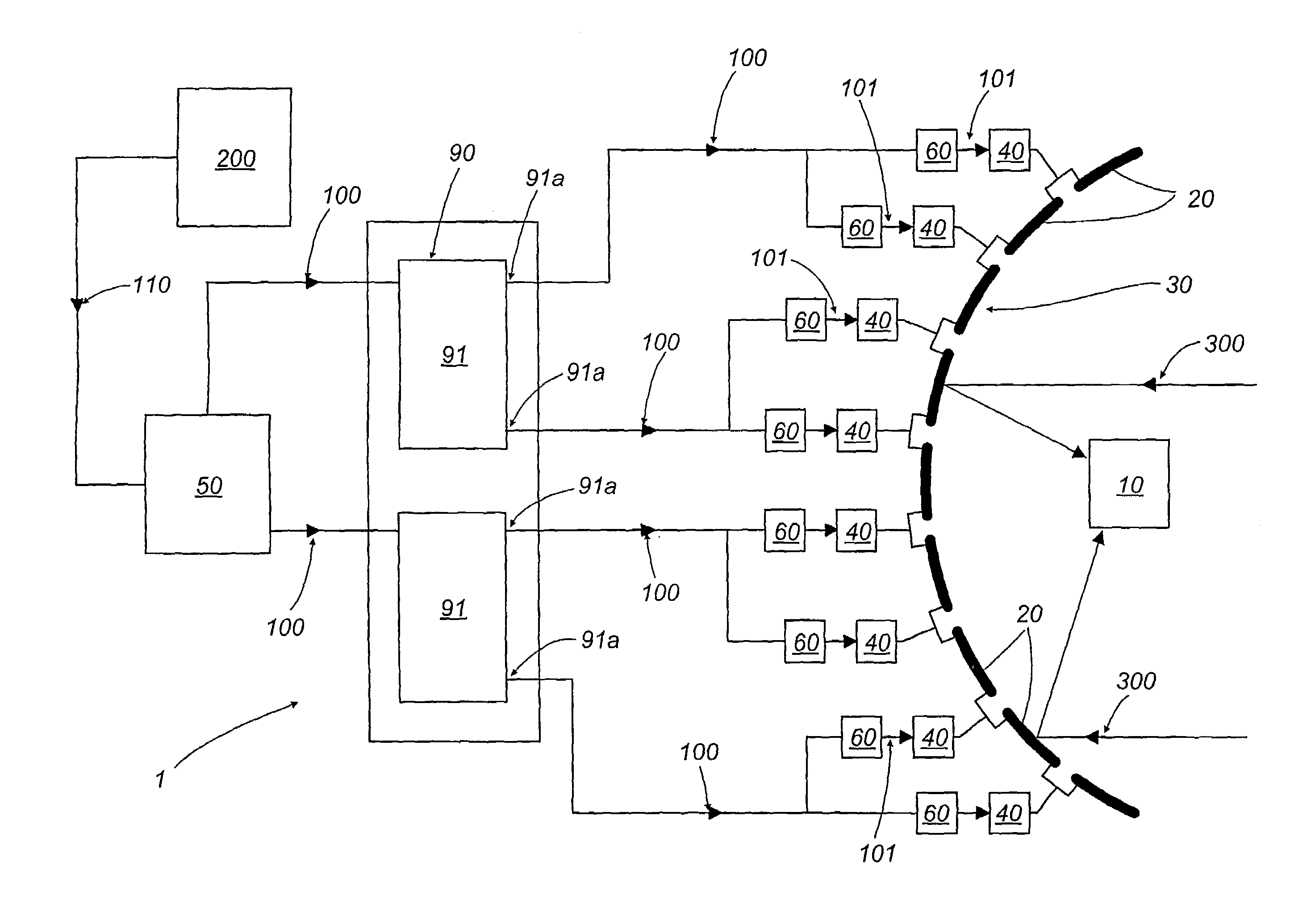
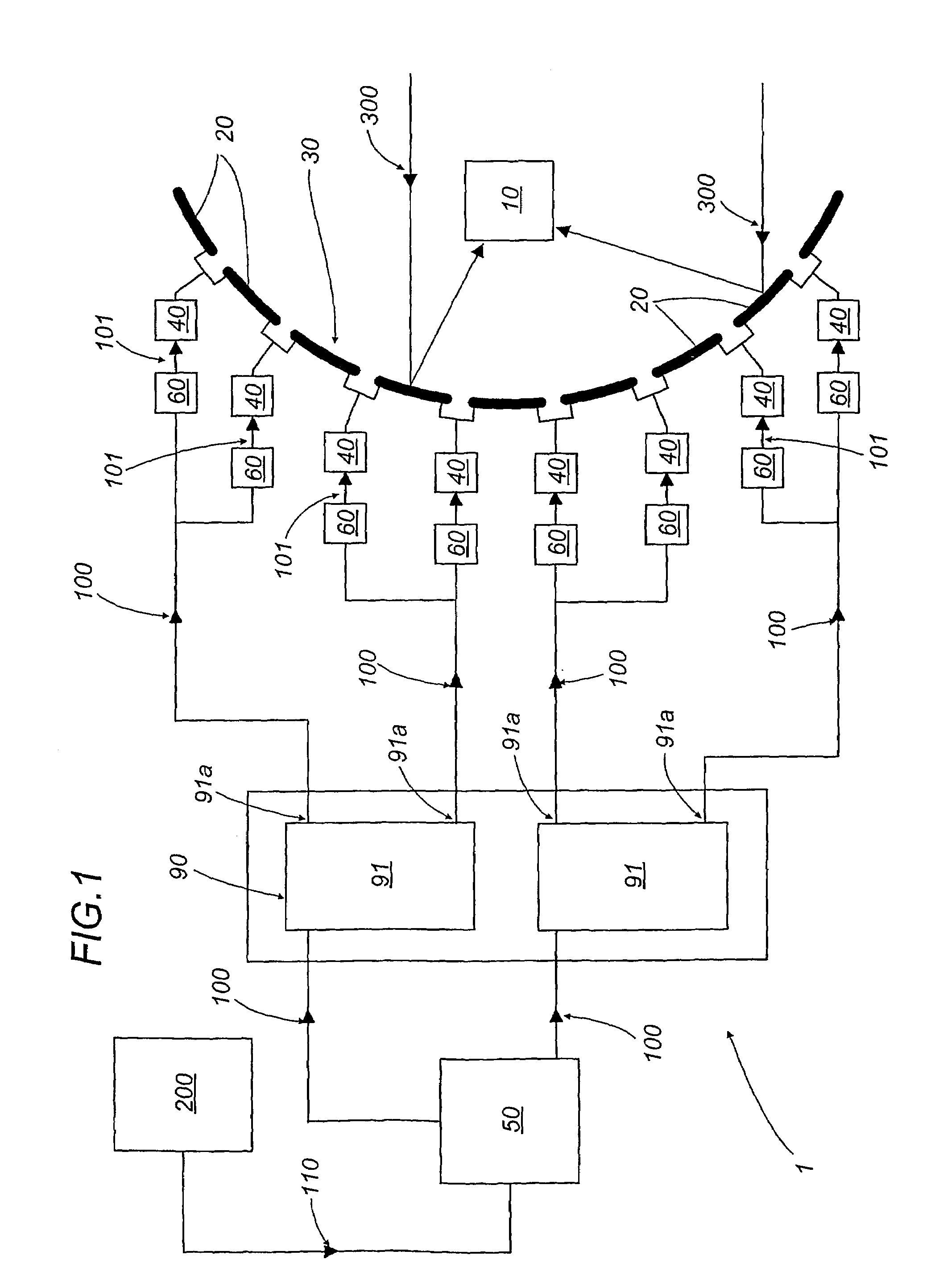
[0037]In the accompanying drawings, the apparatus for detecting electromagnetic radiation according to the present invention is denoted in its entirety by the numeral 1.

[0038]With reference in particular to FIG. 1, the apparatus 1 basically comprises a receiving element 10 designed to detect electromagnetic radiation 300, for example from celestial objects.

[0039]The radiation 300 normally ranges in frequency from a few Ghz to several hundred Ghz.

[0040]The receiving element 10 generates output signals according to the radiation 300 received and addresses these signals to a reception and processing centre where they are analysed in order to obtain desired information.

[0041]In order to direct the electromagnetic radiation 300 at the receiving element 10, the apparatus 1 further comprises a surface 30, whose shape is preferably like that of a paraboloid of revolution and whose curvature can be suitably adjusted to optimise the performance of the aerial.

[0042]Thanks to its reflective pro...


PUM


Abstract

The apparatus for detecting electromagnetic radiation (300), in particular for radio astronomic applications, comprises a receiving element (10), and a plurality of reflecting elements (20) forming a surface (30), capable of receiving the electro-magnetic radiation (300) and to direct it at the receiving element (10) The apparatus (1) further comprises a plurality of actuators (40) used to vary the position of the reflecting elements (20) and a plurality of smart circuit blocks (60), each designed to receive as input a control signal (loo) from a processing unit (50) and to generate as output a corresponding displacement parameter (101) used by an actuator (40) to position the reflecting elements (20) connected to it.

Description

[0001]The application is a 371 of PCT / IB03 / 00045 Jan. 9, 2003.TECHNICAL FIELD[0002]The present invention relates to an apparatus for detecting electromagnetic radiation, in particular for radio astronomic applications.BACKGROUND ART[0003]As is known, there are several different kinds of devices used to detect radiation from celestial objects.[0004]The most common of these devices consist essentially of a parabolic surface made of materials capable of reflecting the radiation concerned (ranging in frequency from a few Ghz to several hundred Ghz), and a receiver positioned at the focus of the parabolic surface.[0005]Using this structure and according to well-known physics laws, the radiation striking the inside surface of the parabolic reflector is reflected at an angle which directs it to the receiving element.[0006]The latter, after detecting the incident radiation, sends corresponding signals containing information about the radiation, to a study centre where the information is ana...

Claims


Application Information

Patent Timeline
Patent Type & Authority Patents(United States)
IPC IPC(8): H01Q15/20H01Q21/24G01R29/10H01Q3/20H01Q15/14H01Q15/16H01Q15/18
CPCH01Q15/165H01Q15/147
Inventor ORFEI, ALESSANDRORODA, JURIZACCHIROLI, GIAMPAOLOMACCAFERRI, GIUSEPPEMORSIANI, MARCO
Owner CONSIGLIO NAT DELLE RICERCHE
Why Eureka
Try Eureka