Quarter wavelength plate and projection type video display device using same

a technology of projection type and projection beam angle, which is applied in the direction of projectors, polarising elements, instruments, etc., can solve the problems of quarter wavelength plate retardation value dependence on incident beam angle, prior art does not take into account, and difficult cooling of quarter wavelength plate b>3/b>, etc., to reduce the influence of dependence, enhance luminance, and reduce the effect of light flux

Inactive Publication Date: 2006-01-03
HITACHI CONSUMER ELECTRONICS CORP
View PDF9 Cites 2 Cited by
  • Summary
  • Abstract
  • Description
  • Claims
  • Application Information

AI Technical Summary

Benefits of technology

[0015]While an increased F-value in the illumination optical system of the reflection type liquid crystal display device could reduce the influence of the dependence on the incident beam angle exerted on the contrast of the reflection type liquid crystal display device, the increased F-value means that a smaller light flux is emitted from a light source, thus excluding the use of a lamp having a large illuminator, for example, a ultra-high pressure mercury...

Problems solved by technology

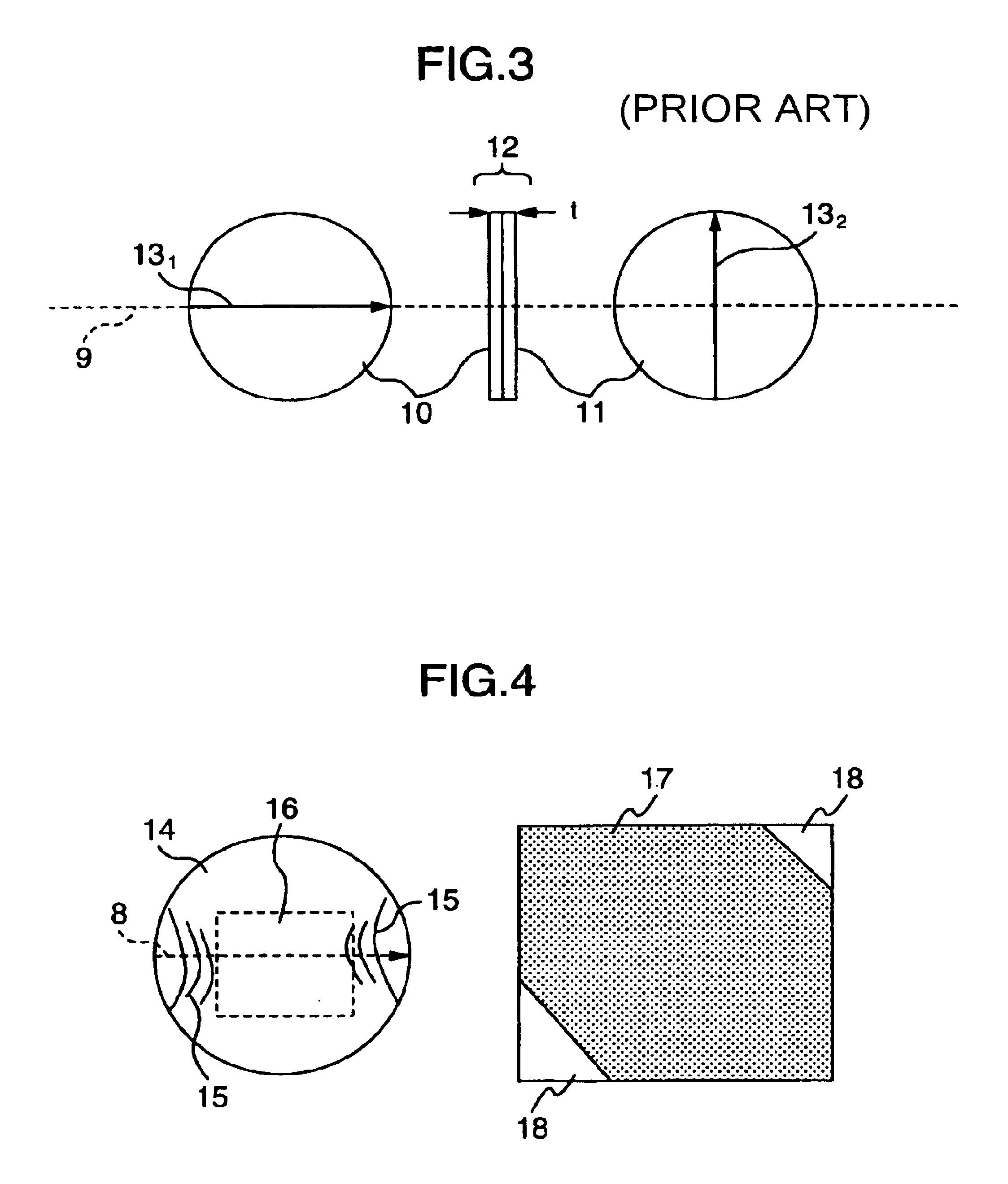
However, with a quarter wavelength plate formed by adhering a phase difference film made of polycarbonate or the like to a substrate, a change in temperature of the quarter wavelength plate causes the phase difference film to distort due to thermal shrinkage of the phase difference film itself, resulting in color shading on the reflection type liquid crystal display device, as will be later described.
It is therefore difficult to cool the quarter wavelength plate 3 down to temperatures at which the liquid crystal display device is free from color shading.
The prior art does not take into consideration the problem on the uneven luminance and color shading.
On the other hand, when a used q...

Method used


Image

  • Quarter wavelength plate and projection type video display device using same
  • Quarter wavelength plate and projection type video display device using same
  • Quarter wavelength plate and projection type video display device using same

Examples


Embodiment Construction

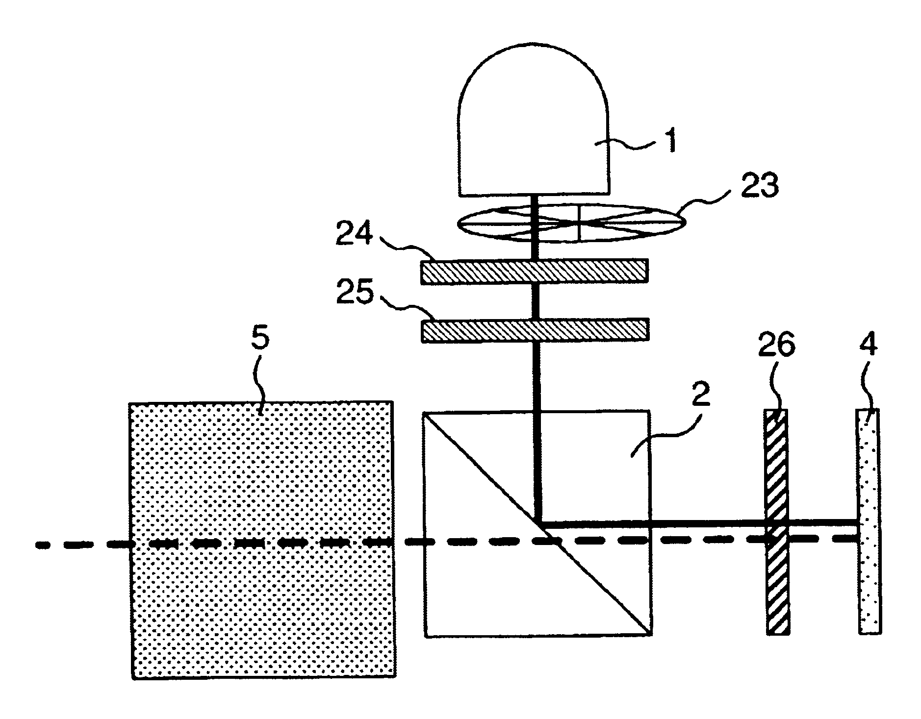
[0029]In the following, embodiments of the present invention will be described in detail with reference to the accompanying drawings. In the drawings, parts identical to those in the previously referenced drawings are designated the same reference numerals, and repeated description will be omitted.

[0030]FIG. 5 is a schematic diagram illustrating a quarter waveform plate according to one embodiment of the present invention which is formed by adhering two optically anisotropic crystals with their phase delay axis oriented orthogonal to each other. The quarter wavelength plate has a thickness of 0.1 mm or more and 0.5 mm or less.

[0031]In FIG. 5, the quarter wavelength plate 112 comprises a first optically anisotropic crystal 110 having a phase delay axis 131 oriented in parallel with a reference axis 9; and a second optically anisotropic crystal 111 having a phase delay axis 132 oriented perpendicular to the reference axis 9. The quarter wavelength plate 112 is formed by adhering the f...


PUM


Abstract

A quarter wavelength plate for reducing the dependence of a retardation value on an incident beam angle in optically anisotropic crystals. The quarter wavelength plate is formed of optically anisotropic crystals in a thickness of 0.1 mm to 0.5 mm. The quarter wavelength plate can contribute to a reduction in the dependence of the retardation value on the angle at which a light beam impinges on the quarter wavelength plate, and to a reduction in color shading caused by a rise in temperature. A reflection type liquid crystal display device which employs the quarter wavelength plate can enhance the luminance and contrast.

Description

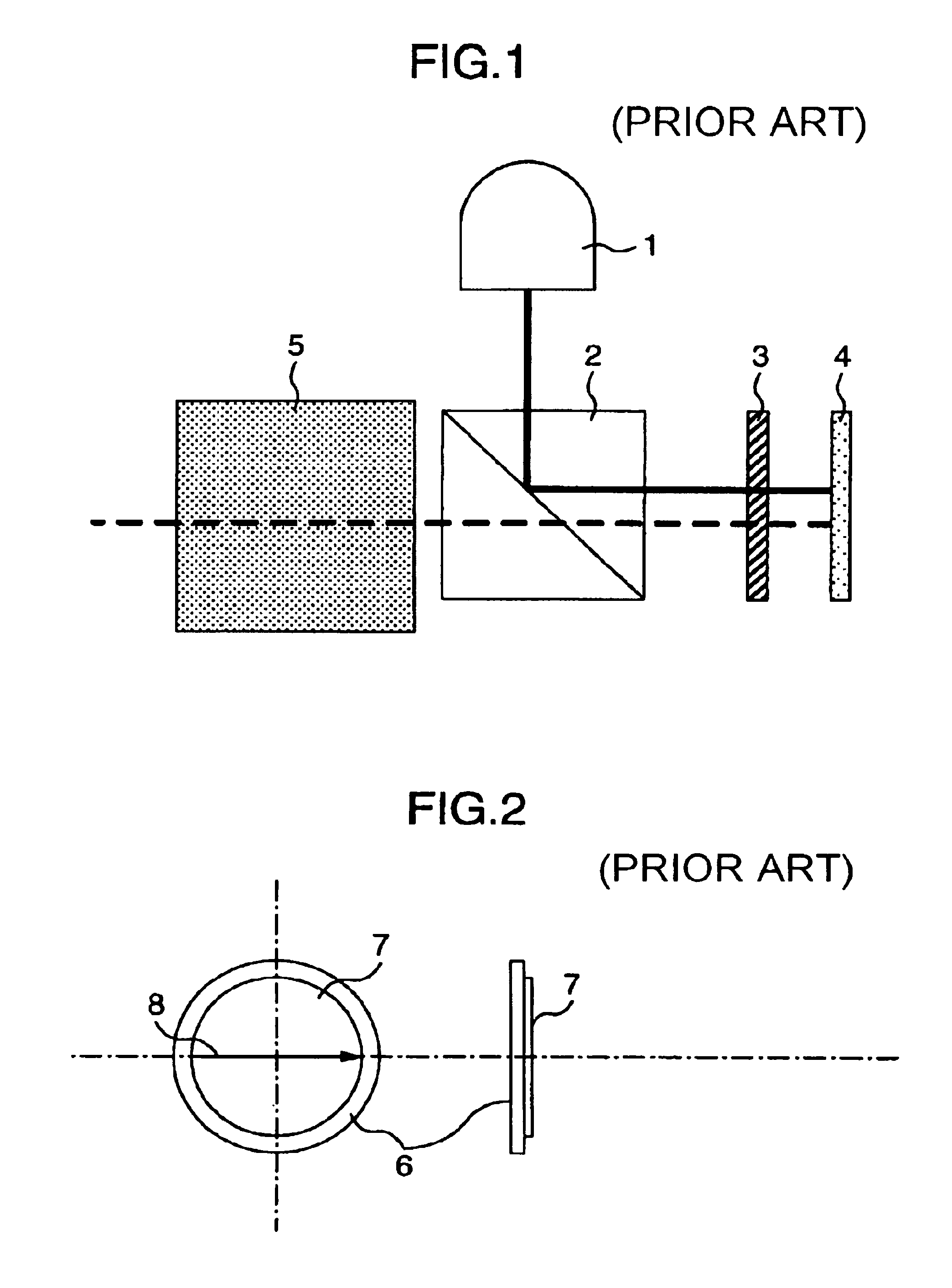
BACKGROUND OF THE INVENTION[0001]The present invention relates to a quarter wavelength plate which is particularly advantageous in enhancing the contrast, and an optical unit using the same for use in a reflection type liquid crystal display device.[0002]A reflection type liquid crystal display device using a reflex liquid crystal display element for displaying images is disclosed, for example, in JP-B-7-38050.[0003]FIG. 1 is a schematic diagram illustrating an optical unit in the reflection type liquid crystal display device disclosed in the above-cited document. The optical unit herein referred to is assumed to be an optical display device which comprises a light source, an illumination optical system, a video display element, and a projection lens. The video display element is irradiated with light from the light source through the illumination optical system. A light intensity modulation is performed for converting the irradiated light to the contract of each pixel on the video ...

Claims


Application Information

Patent Timeline
IPC IPC(8): G02F1/1335G02B5/30G02F1/13363G03B21/00
CPCG03B21/00G03B21/006G02B27/28
Inventor SHIKITA, KAZUONAKASHIMA, TSUTOMUKIMURA, NOBUYUKI
Owner HITACHI CONSUMER ELECTRONICS CORP
Why Eureka
Try Eureka