Datapipe routing bridge

a datapipe and routing bridge technology, applied in data switching networks, multiplex communication, instruments, etc., can solve the problems of reducing the number of external pins/components and the complexity of operation, and the limitation of the number of processors that can be connected together, so as to reduce the number of external pins, improve the inter-processor traffic management, and remove the limitation of how many processors can be connected together

Active Publication Date: 2006-01-03
TEXAS INSTR INC
View PDF13 Cites 21 Cited by
  • Summary
  • Abstract
  • Description
  • Claims
  • Application Information

AI Technical Summary

Benefits of technology

[0009]1. It eliminates external components and reduces the number of external pins dedicated to inter-processor communication, while at the same time it removes any limitations on the scope of communication, packet size and the types of connection topologies.
[0010]2. It hides the space / time complexity of moving large amounts of data between many nodes over a fixed number of links by autonomously performing all routing functions without involving the local CPUs or DMAs.
[0011]3. It removes any limits on how many processors can be connected together.
[0012]4. It removes any limits on how many digital signal processors can receive the same data stream as it flows around the datapipe network (broadcast / cell mode).
[0013]5. The capability of this new method to multiplex data and control elements on the same transfer links between digital signal processors, improves inter-processor traffic management, by the ability of control elements to configure or change the path for the data elements that follow. Previous methods had to use different mechanisms to transport control and data information, negatively impacting loading / synchronization or management of on-chip peripherals that could otherwise concentrate on processing the application.
[0014]6. The datapipe bus ready signal improves inter-processor traffic management by autonomously propagating a not ready condition against the flow of data, to manage congestion of some transfer link segments without involvement of any chip resources. This autonomous traffic management is better than the hands-on traffic management of previous methods, because it releases valuable chip resources from having to be involved in traffic management and instead allows them to fully concentrate of the application tasks at hand.

Problems solved by technology

All current methods of inter-digital signal processor traffic management have a negative impact on the loading of the central processor unit (CPU) and the direct memory access (DMA) function.
In addition there is a negative impact on the number of external pins / components and the complexity of operation.
Conventional methods also have confining limits on the number of processors that can be connected together and the manner in which they may be connected together.
The data streams used in current methods do not have means to carry control elements for transfer path reconfiguration ahead of the data packets, or for propagating a not ready signal up the stream to prevent data overruns.
These limitations force the CPU / DMA and other chip resources to be actively involved in data traffic management at the cost of fewer cycles available to processing of data.
The current methods also do not allow multiple digital signal processors to collectively receive the same data stream.

Method used


Image

  • Datapipe routing bridge
  • Datapipe routing bridge
  • Datapipe routing bridge

Examples


Embodiment Construction

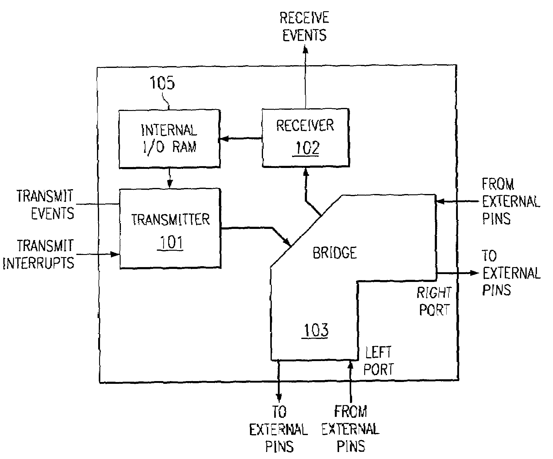
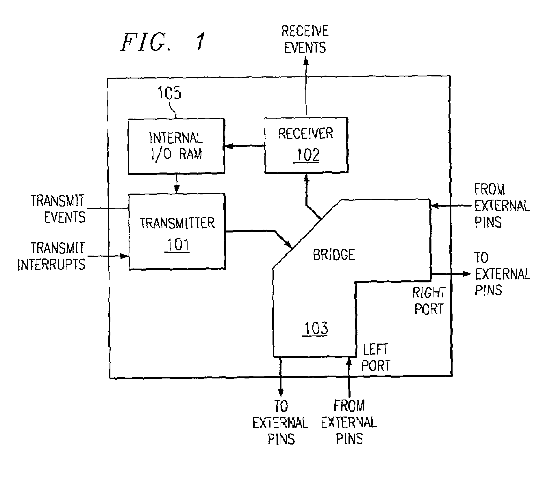
[0041]This application uses the descriptive name datapipe routing bridge or simply datapipe to describe a packet based communications peripheral connecting multiple processors without glue logic or CPU intervention. FIG. 1 illustrates the makeup of a datapipe. It is composed of three building blocks transmitter 101, bridge 103 and receiver 102. The main function of the bridge component is to provide high levels of connectivity between multiple digital signal processors without paying the penalties usually associated with inter-processor connections. Dedicated routing logic within the datapipe autonomously navigates data packets of programmable size along the shortest distance from the source processor to one or more destination processors. Transmitter 101 may transmit data packets via bridge 103 to one or both of the right and left ports. Transmitter 101 responds to transmit events and transmit interrupts from an associated data processor (not shown) to supply data from internal I / O...


PUM


Abstract

The datapipe routing bridge is composed of three building blocks, transmitter, bridge and receiver. The bridge component provides high levels of connectivity between multiple digital signal processors without paying the penalties usually associated with inter-processor connections. The individual digital signal processors are connected with unidirectional point-to-point links from a bridge terminal on one digital signal processor to a bridge terminal on another digital signal processor. A real-time comparison of the packet header information with direction identification codes (IDs) stored inside the bridge routes individual data transfer packets arriving at the bridge into the local processor, repeated out to the next processor or simultaneously absorbed and repeated.

Description

CROSS REFERENCE TO RELATED APPLICATION[0001]This application claims priority under 35 USC §119(e)(1) of Provisional Application No. 60 / 224,607, filed Aug. 11, 2000.[0002]This application is related to the following copeding application:[0003]U.S. Provisional Application No. 60 / 224,913 entitled PULL TRANSFERS AND TRANSFER RECEIPT CONFIRMATION IN A DATAPIPE ROUTING BRIDGE now U.S. patent application Ser. No. 09 / 905,379; and[0004]U.S. Provisional Application No. 60 / 224,586 entitled MULTIPROCESSOR NETWORK NODE FAILURE DETECTION AND RECOVERY now U.S. patent application Ser. No. 09 / 904,991.TECHNICAL FIELD OF THE INVENTION[0005]The technical field of this invention is data communication among a plurality of data processors.BACKGROUND OF THE INVENTION[0006]All current methods of inter-digital signal processor traffic management have a negative impact on the loading of the central processor unit (CPU) and the direct memory access (DMA) function. In addition there is a negative impact on the ...

Claims


Application Information

Patent Timeline
Patent Type & Authority Patents(United States)
IPC IPC(8): H04L12/28G06F13/00H04L12/56G06F13/36H04L12/46
CPCH04L12/4625
Inventor GALICKI, PETERSHEPHERD, CHERYL S.THORN, JONATHAN H.
Owner TEXAS INSTR INC
Why Eureka
Try Eureka