Apparatus and method for converting signals

a technology of converting apparatus and signals, applied in the field of apparatus and methods for converting signals, can solve the problems of large and complex image-coding format converting apparatus, time delay, and difficulty in real-time processing of image signals, and achieve the effect of small and simple structur

Inactive Publication Date: 2006-01-03
SONY CORP
View PDF9 Cites 30 Cited by
  • Summary
  • Abstract
  • Description
  • Claims
  • Application Information

AI Technical Summary

Benefits of technology

[0012]The present invention has been made in view of the above. An object of the invention is to provide an apparatus and method for converting signals, in which at least a resolution-converting process is performed on a signal encoded in the first format, such as a bit stream of MPEG2 image codes, thereby generating a second signal, and a third signal, such as a bit stream of MPEG2 image codes, is generated from the second signal. The third signal thus generated preserves the quality of the first signal. The third signal can be generated by processing a small amount of data. The apparatus can therefore be relatively small and simple in structure.
[0017]In the apparatus according to the present invention, at least resolution conversion is performed on a first signal, thereby generating a second signal, and a third signal is generated from the second signal. The process parameters contained in the first signal are converted to all or some of the parameters that are required to generate the third signal. Hence, the amount of data that should be processed to generate the third signal from the second signal can be reduced, without deteriorating the quality of the third signal. This prevents the apparatus from becoming large and complex.

Problems solved by technology

Consequently, it is difficult to process the image signal in real time.
This will inevitably result in a time delay.
Further, the image-coding format converting apparatus needs to be large and complex.
Therefore, the resolution and frame rate of the image signal output from the resolution / frame rate converter 211 may not be appropriate, making it difficult for the MPEG4 image encoder 212 to perform MPEG4 image encoding correctly.

Method used


Image

  • Apparatus and method for converting signals
  • Apparatus and method for converting signals
  • Apparatus and method for converting signals

Examples


first embodiment

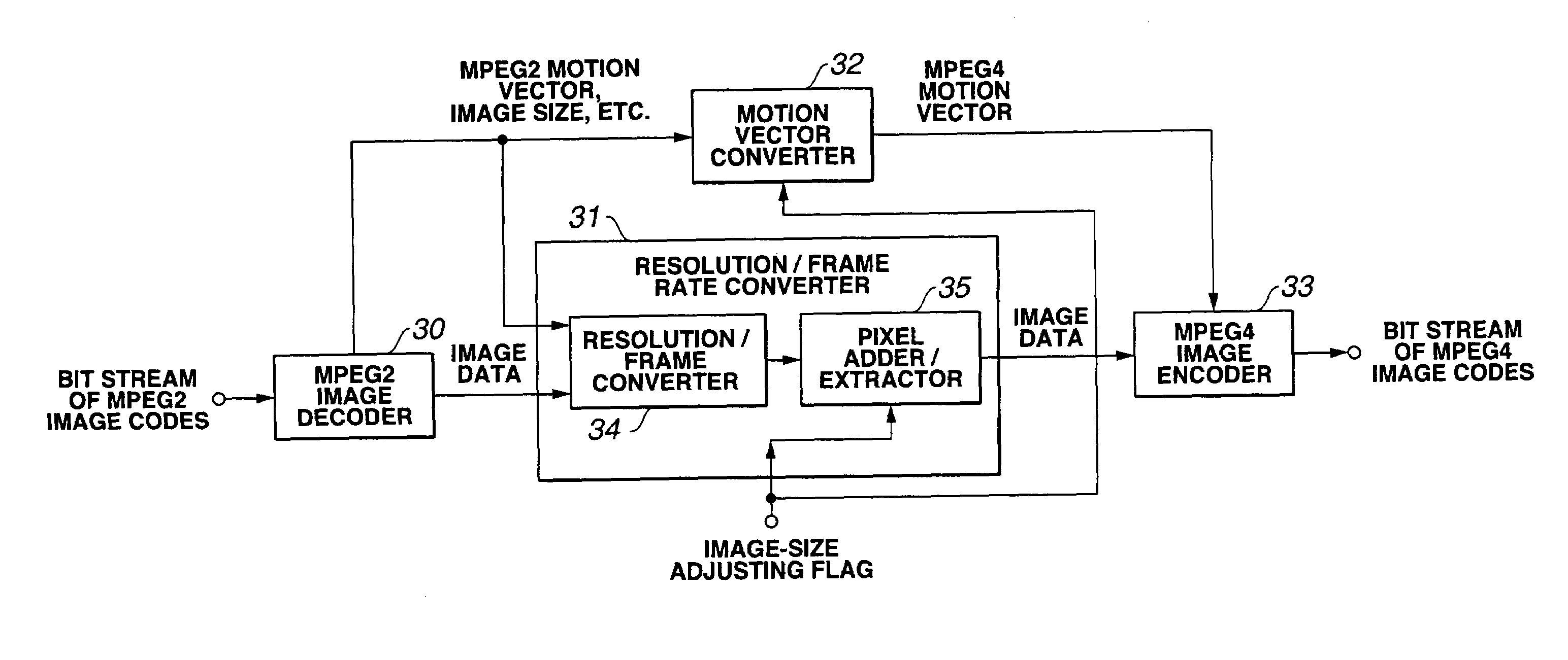
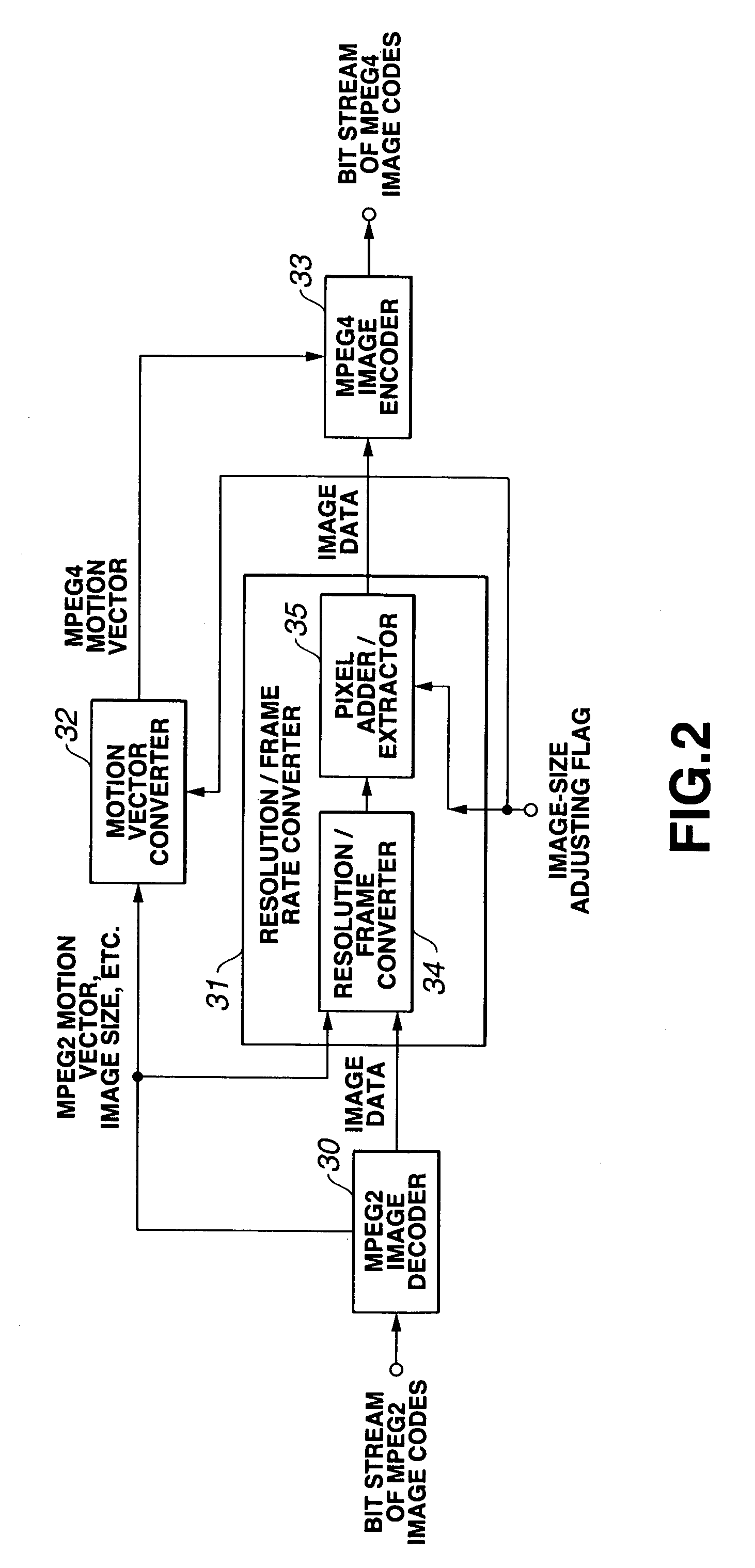
[0035]FIG. 2 shows an apparatus for converting an image-coding format, which is the invention.

[0036]In the apparatus shown in FIG. 2, an input bit stream of MPEG2 image codes is supplied to the MPEG2 image decoder 30.

[0037]The MPEG2 image decoder 30 decodes the bit stream in accordance with the MPEG2 image-decoding scheme, thus generating an image signal. The image signal (an interlace image signal) is input to the resolution / frame rate converter 31.

[0038]The resolution / frame rate converter 31 converts the image signal to an image signal that has a given resolution and a given frame rate. The converter 31 adjusts the resolution of the image signal in accordance with an image-size adjusting flag supplied from an external device. Thus, the section 31 outputs an image signal having such a resolution that the image signal may be converted into an MPEG4 image signal. The image signal the resolution / frame rate converter 211 has generated is supplied to the MPEG4 image encoder 33.

[0039]The...

second embodiment

[0136]In the second embodiment, the motion vector of the 16×16 pixel macro block and the motion vector of the 8×8 pixel block are detected before they are supplied to the MPEG4 image encoder 33. Therefore, of the image signal stored in the frame memory 154, the image signal supplied from the resolution / frame rate converter 31 represents the present frame image, and the image signal supplied from the MPEG4 image encoder 33 represents a prediction-reference frame image. The motion compensation predictor 155 uses the present frame image and the prediction-reference frame image, thereby detecting an MPEG4 motion vector that pertains to these frame images. The prediction-reference frame image may be represented by an image signal output from the resolution / frame rate converter 31. Further, the image signals output from the resolution / frame rate converter 31 may alternately represent the present frame image and the prediction-reference frame image. The MPEG4 motion vector output from the ...

third embodiment

[0137]FIG. 16 shows an image-coding format converting apparatus that is the present invention.

[0138]As illustrated in FIG. 16, this image-coding format converting apparatus comprises an image pre-processing filter 161, a motion compensator 162, an MPEG2 image encoder 163, a motion vector converter 164, an MPEG4 encoder 165, and a resolution / frame rate converter 166. The image pre-processing filter 161 receives an image signal from an imaging device 160 or an image-receiving device 167. The imaging device 160 has, for example, a CCD (solid-state imaging element). The image-receiving device 167 is, for example, a tuner or the like. The image pre-processing filter 161 performs, if necessary, pre-processing on the input image signal, thereby removing noise from the image signal. The image signal is supplied from the image pre-processing filter 161 to the motion compensator 162, MPEG2 image encoder 163, motion vector converter 164 and resolution / frame rate converter 166. If the image sig...


PUM


Abstract

An image-coding format converting apparatus comprising an EMPEG2 image decoder 30, a resolution / frame rate converter 31, a motion vector converter 32, and an MPEG4 encoder 33. The EMPEG2 decoder 30 decodes a bit stream of EMPEG2 image codes, generating an image signal. The resolution / frame rate converter 31 converts the image signal. The MPEG4 encoder 33 encodes the output of the resolution / frame rate converter 31, generating a bit stream of MPEG4 image codes. In the resolution / frame rate converter 31, pixels are added or extracted in accordance with the start position of a macro block, thus adjusting the input image signal to one than can easily be encoded to MPEG4 image codes. The motion vector converter 32 generates an MPEG4 motion vector from parameters such as an MPEG2 motion vector. The MPEG4 encoder 33 uses the MPEG4 motion vector to encode the output of the resolution / frame rate converter 31.

Description

RELATED APPLICATION DATA[0001]The present application claims priority to Japanese Application No. P2000-050524 filed Feb. 22, 2000, which application is incorporated herein by reference to the extent permitted by law.BACKGROUND OF THE INVENTION[0002]The present invention relates to an apparatus and method for converting signals. More particularly, the invention relates to the technique of converting a signal encoded in the first format, into a signal encoded in the second format.[0003]FIG. 1 shows a conventional apparatus for converting an image-coding format. The apparatus is designed to convert an input bit stream of image codes into a bit stream of a different image-coding format. More specifically, the image-coding format converting apparatus of in FIG. 1 converts an input bit stream of MPEG2 (Moving Picture image coding Experts Group: ISO / IEC13818-2) image codes, into a bit stream of MPEG4 (ISO / IEC14496-2) image codes.[0004]In the image-coding format converting apparatus shown ...

Claims


Application Information

Patent Timeline
Patent Type & Authority Patents(United States)
IPC IPC(8): H04N7/12H04N19/50H03M7/00H04N5/46H04N5/92H04N7/46H04N11/20H04N19/105H04N19/137H04N19/176H04N19/40H04N19/42H04N19/51H04N19/513H04N19/59H04N19/80H04N19/91
CPCH04N5/4401H04N5/46H04N21/440218H04N21/440263H04N21/440281H04N19/577H04N19/112H04N19/132H04N19/137H04N19/587H04N19/40H04N19/59H04N19/105H04N11/20H04N21/426
Inventor YIWEN, ZHUYAGASAKI, YOICHINAGUMO, TAKEFUMITAKAHASHI, KUNIAKI
Owner SONY CORP
Why Eureka
Try Eureka